Scheme of connecting the burners of the Hephaestus electric stove. Repair, connection of electric stoves - their electrical circuits
A modern electric stove can be a great alternative to the usual gas stove. Gone are the days when this household appliance looked bulky and consumed an exorbitant amount of electricity.
Today, the market for electric stoves is very diverse. In each model, manufacturers have tried to harmoniously combine the functionality, compact design and energy saving technologies.
In order not to turn to a professional electrician, you need to know how to connect an electric stove yourself. Most works, and sometimes the installation of such equipment in full, you can do it yourself.
Before you connect the electric stove yourself, you should find out its power, and also determine what type of network you need to connect to. Most private houses and apartments are equipped with common network single-phase wiring (220 volts). Three-phase lines are less common.
- Tabletop electric ranges and stand-alone ovens are less than 3000 watts. They can be connected via a plug (13 Amp) and a socket or via a fused connector.
- Electric stoves with an oven have a power of more than 3000 watts. Their connection is carried out through a separate wiring that goes directly to the electrical panel. This type of wiring is called a radial network.
For this type of network, the appliance is connected without an outlet to increase security. The power chain is extended, installed fuse. Regarding it, you can (and even need) to consult an electrician. He will tell you whether it is worth replacing the traditional mini-machine with a fuse of this type.
A separate breaker with a fuse is mounted in the electrical panel or an existing free block is used. It must have a fuse. When installing a knife switch, make sure that tubular fuses are suitable for it.
The radial network is selected as follows:
- stoves up to 13.5 kW - 4 sq. mm;
- up to 18 kW - 6 sq. mm.
Protection is carried out by a 30 amp fuse or a 32 amp mini-machine. Three wire wiring. One of the cores is used as a ground.
We figure out how to properly connect the electric stove to the radial network
 Wiring diagram electric stove with your own hands in this case, you should do it in the following order.
Features of installation via connecting device
 The procedure for this installation is as follows:
- If the switch block goes directly to the spare block of the electrical panel, the red core of the wire is connected to the block itself (this is a phase), the black one to the neutral bus, and the ground wire, respectively, to the ground bus (marked with yellow-green cambric).
- The second connection option is through a switch equipped with a fuse. It is attached near the electrical panel with screws.
The wires from the stove are connected to the terminals as follows:
- a core with red insulation is attached to the phase;
- black - to neutral;
- the ground conductor is connected to the corresponding terminal (marked with a two-color cambric).
It is connected to the circuit breaker using two double-insulated stranded wires. Section 16 sq. mm (you can take wires thinner, by 10 sq. mm and connect with shorter segments of these wires). The black wire is attached to the neutral terminal of the switchboard and switch (N). Red to phase (L). Grounding from a stranded wire of the same length is fixed on the terminal in the corresponding place of the shield (yellow-green color).
Then the fuse and cover are installed electrical panel closes.
Attention! It is impossible to connect to a common terminal in the same way as it is impossible to power a new network until the installation is checked by a professional electrician and they issue a conclusion on compliance with all technical standards. This document is submitted to the electric company along with a request to connect to its network.
Mounting methods for different circuits
When installing with an outlet, everything is much easier. A cable is used to connect an electric stove with a special connector - a pair of sockets and plugs (RSh-VSh). It is produced in two types: for hidden and. 
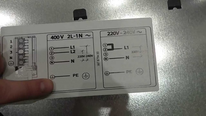
Plates come with a power of 220 and 380 volts. The connection diagram must be indicated by the manufacturer to ensure the correct connection of the network wires to the plate terminals. This schematic drawing is often located on the back of the device, or in the instructions for it.
On a note. In the diagram, the terminals for the phases are indicated: L1, L2, L3; neutral ones are indicated by the letter N. Directly in the terminal box, the phase is marked with numbers: 1, 2, 3; neutral is 4 and 5.

- The jumper between the phase terminals was initially set by the manufacturer "by default" to connect the electric stove to a single-phase network.
- For a three-phase connection of the electric stove, the jumper is removed. The order in which the wires are connected to the phase terminals does not matter.
- For two-phase wiring, a jumper is installed between terminal 1 and 2. One phase is connected. The second is attached to the clamp number 3.
An example of a single-phase connection of an electric stove can be seen in the figure.
The principle of installation with all the variety of plates on the market is standard. Built-in, ordinary household and even industrial electric stoves are connected according to one general scheme. Minor nuances are due to the number of phases in the network. Understanding this is quite easy. Therefore, in fact, any owner will cope with the connection of the electric stove.
Video about connecting an electric stove with your own hands
Not all localities have gas supplied to residential buildings. In such situations, one has to electric hotplates. Old models are still in use. They sometimes experience unpleasant situations that require the replacement of certain elements. It would be useful to connect the burner, because it is often the heating elements that fail and require replacement.
Common Models
By design, heating elements for old tiles should not break, but it still happens. This may be due to the fact that the tile heater has been idle for a long time after it was forgotten to turn off, or there is a sharp power surge that affects the burner. If mechanical damage in the form of cracks is visible on the surface of the heating element, then we can say for sure that it warmed up to very high temperatures. Initially, the connection diagram is in the product passport. In the case of its satisfactory condition, it is easy to clarify, but most often such documents are lost or have already been thrown away, then you can use the guide that will be given in the article.
Elektra

Electra is one of those stoves that were installed in new buildings or purchased on their own. We are talking about a stove with model number 1002. The circuit that was developed by the designers for connecting is not particularly difficult, so even a person who is far from electricity can figure it out. On the top of the plate are four heating element. Each of them is indicated by a number from 1 to 4 and has a letter index "H". The first two burners of the stove are exactly heating elements, i.e. tubular heaters. Item under serial number 3 is made of cast iron and has a large diameter of 20 cm. The fourth element is made similar to the third, but its diameter is slightly smaller and is 14 cm.

Each burner has its own switch. They also have a digital designation, but the first two have a prefix from the letter "P", and the third and fourth - from the letter "P". The latter have the advantage of adjusting the power in seven steps, which allows you to select the desired mode. The oven of a plate has a separate regulator on three provisions. It is abbreviated "PS". Indicator lamps in the diagram are marked with the letter "L" and a serial number from 1 to 4, which also corresponds to the burner number. For oven also has its own lamp, which is marked with the number 5. There are two more heating elements in the oven, which are marked with the numbers 5 and 6 with the corresponding letter. The seventh heater is located at the top of the oven and is a grill.

Replacing any of the heating elements is that it is first dismantled from the tile. To do this, you will have to remove the protective caps and trims. During disassembly, you can trace where the conductors from a particular heater go in the stove. If the wires have melted, then you can clarify this point according to the diagram given above. It also contains the procedure for connecting the power line. The new heater is simply installed in the stove, fixed and connected.
Dream

Even more popular than Elektra was the Dream stove with model number 8. It is a small oven, on the upper edge of which there are two heating elements. On the diagrams for this stove, the heaters that are on the burners are indicated by the numbers 1 and 2, next to them is the letter index "E". Heaters 3 to 5 are inside the oven. The main module, thanks to which the adjustment is performed, is indicated by the numbers 1 to 4 and has the index S. The design provides light indicators. They could signal the operation of the burners, heating elements inside the oven and just the backlight. In the passport, they are designated as HL and have numbers from 1 to 3.
Note! On the diagram you can also find an element with the designation T-300. This is a thermal relay that was responsible for turning off when a certain temperature was reached.
The stove has the ability to control the intensity of heating. It is produced by switch S1. Due to the closing of the contacts, the electric current flows from the plug, which is designated XP, and through the fuse F is supplied to the heater, which is located in the oven. It is connected in series with the rest of the heating elements that are in the oven. This means that before replacing, it is necessary to determine which particular heater has failed. This can be done by changing the position of the switch to such a position that power is supplied separately to one or two heaters in the oven. Each burner also has its own switch. The diagram shows how the wires go to connect each individual heater.
Lysva
Another manufacturer who has met quite often before is Lysva. For example, below is a diagram that will allow you to replace a burner on a stove that has three main heaters and those in the oven. Each heater on the burner has 6 adjustment modes. The task is performed by increasing or decreasing the resistance of the conductors. The diagram shows the installed resistors. Three of them go to each heating element and four more to the oven. Guided by how the current flows through the circuit, you can easily install a new heater. At the end of the article there will be a video about connecting a burner with four leads.
Before proceeding with the replacement of the element on the stove, you need to make sure that it is really out of order. It is almost impossible to do this with an ordinary dial tone, because the heating element has its own resistance. It is the resistance that needs to be checked. The manufacturer specifies what value is normal for a healthy node. It is necessary to fix two multimeter probes on the heater contacts and switch to the resistance measurement mode. At the end of the process, it is necessary to check the reference value.

Note! Resistance measurement must be made on the dismantled heater, otherwise the value of the entire system will be displayed.
During installation, be careful at the connection points. All bare wires must be insulated with electrical tape or heat shrink tubing. Not a single bare wire should touch the body of the stove. When performing replacement work, it is necessary to de-energize the stove. All tools to be used must have dielectric handles that will not miss the discharge that may be in capacitors if they are present in the circuit.
Conclusion
As you can see, having a diagram, it is not so difficult to replace the heater. You should never rush to disconnect any wires. It is better to start taking pictures of them on a smartphone or digital camera to know how to connect in reverse order.
To necessary tools to connect include the following:
- a puncher and a grinder for the formation of strobes, seats for sockets, with surface cable routing, which is highly discouraged, such tools will not be needed;
- cable pliers;
- screwdriver;
- indicator;
- drill;
- measuring devices for marking the position of all elements of the chain;
- insulating material;
The only problem is education seat in the wall under the socket and cable. The rest of the work is simple and can be done without any problems.
Schemes for connecting electric stoves
single phase

The most common scheme, since in residential premises there is no three-phase power supply in 90% of cases. In this case, one phase is connected to the terminals L1, L2, L Copper jumpers are installed between these terminals, which often come with the stove. A jumper is also installed between terminals N1 and N2 and the “zero” cable is connected to them. There is a special "earth" for the core.
Two-phase system

Used quite rarely. Often, in the country, you can find a situation where there are only two phases with a three-phase power supply. In this case, a two-phase connection system is used: a jumper is installed between terminals L1 and L2 and phase A is connected, and phase B is thrown to terminal L3. "Earth" and "zero" are connected in a similar way.
Three-phase system

Somewhat different from the above. The main difference is that you don't need to use any jumpers. Phase A is connected to terminal L1, phase B to terminal L2, and C to terminal L "Ground" and "zero" are also connected according to the previous diagrams.
Similar features relate to the connection diagrams of the electric stove.
Step-by-step instruction
 First, let's highlight some of the nuances:
- You should create a plan for the future food chain.
- According to the plan we mark the future location electric cable, sockets and .
- We carry out the creation of strobes under the electrical cable. It is recommended to deepen a few centimeters, since concrete, brick have good dielectric properties, and also do not ignite. Such a recess will protect the cable from mechanical damage, and Decoration Materials from fire during insulation breakdown.
- We carry out the creation of a landing hole for the outlet. It is worth remembering that the more accurately it was done, the better mount sockets. Otherwise, it may wobble.
- After the previous work has been done, we lay the cable, connect it to the outlet. At the same time, we note that the connection of several pieces of cable is not allowed.
- We carry out the connection of the power plug to the plate according to the above diagrams.
- If the machine is connected to the network, you need to install it in the electrical panel.
- We connect the cable to the machine or other power source.
When carrying out work, it should be remembered that the network must be de-energized. To do this, the circuit is first disconnected from the energy source, and then the presence of current on all branches is checked using an indicator or a multimeter. It is worth remembering that when cutting the cable, you should leave the ends with a margin.
 Connecting the power plug or cable directly (not recommended) can be done as follows:
- Opening the back cover of the stove and get access to the terminals through which power will be supplied.
- A massive block is hidden under the back cover. We carry out unscrewing the bolts by half.
- We clean the ends of the wire strands so that there are enough of them to trace around the bolt. At the same time, it is worth noting that their large length is the main mistake. Under some circumstances, there is a possibility that the strands will touch and a short circuit will occur.
- We bend the ends of the veins and throw them on top of the bolts. We breed the veins to the maximum distance.
- We twist the bolts without applying excessive force. Excessive force can lead to a violation of the structure of the villi. However, the cores must have a strong connection.
- We close the lid.
Possible difficulties:
- The formation of the correct niche for the outlet. For perforators, special nozzles were created that allow you to create a niche of the required shape and size.
- You can often meet the situation when the kit does not include the jumpers necessary to complete the work of connecting the stove. You can create a jumper yourself, for which you can use a small piece of the wire used. This feature means that the jumper will have transverse section, chosen taking into account the minimum allowable value.
- You can meet a situation where the cut cable is not enough. In this case, it is worth remembering that the presence of connections between pieces of cable in this case is not allowed. This feature is due to the fact that it is at the joints that the greatest resistance and heating is created. The insulation used may not be able to withstand the load.
Some problems cannot be fixed on their own. Previously, a common occurrence was the situation when a common machine for an apartment or house could not withstand the load. Its replacement can only be carried out by employees of the power grid.
Grounding guide
 When working in old-style networks, even experts often make gross mistakes. An example is the case when grounding is performed on the operating zero bus. In a situation where the current is cut off by the wire, it is supplied to the appliance and the user will be shocked. Also, you can often find a situation where the "zero" lived and the phase is confused.
The result of such connection will also result in electric shock to the user. However, it is impossible to refuse to connect "zero".
First, you should find out if the shield has a ground. To do this, you can use the help of an electrician or visit the Housing Office, another service organization with a similar question.
The answer to the question must be given clearly, supporting documentation must be provided. Otherwise, you should not believe the words.
Residents on the ground floor or own house can solve the problem like this:
- Outside three pipes with a length of 250 centimeters and a diameter of at least 16 millimeters are dug in.
- They are connected between themselves.
- ferrule wire from the shield is led to the dug-in pipes.
- We make connections e zero bus.
In a similar way, you can create an outlet circuit for electricity.
If it is not possible to create a diversion circuit, follow the instructions below:
- Plugging the wire, which is responsible for "zero".
- When installing the plate we pay attention to the fact that it is not in contact with other electrically conductive elements, for example, with pipes.
- Near the stove you should put a dry mat that has dielectric properties.
- regular machine change to a differential model with a limit of 30 A.
- Showing Caution when using the plate.
Requirements for wiring and other circuit elements
 selection of cable section
 There are several basic requirements that must be met in order to reliable operation electric stove. These requirements are due to the fact that the considered consumer of electricity has a large capacity and this creates a certain voltage in the network.
Increasing the voltage leads to heating of the wiring and other elements if they were not designed for such a load.
The main requirements for electrical wiring include the following:
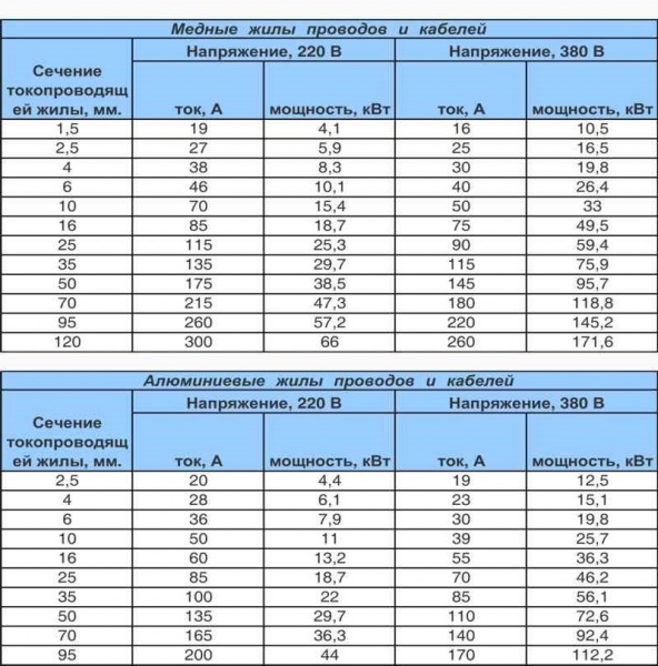
- One of the points of the PUE defines that only copper wires can be used in residential premises. Use aluminum wires in residential premises is possible only if their cross section is 16 square meters. mm and above this indicator. It is not worth using wiring of this section at home. This feature is associated with many features of the considered alloys, from which the wiring is made.
- If at home or in an apartment single-phase power, a three-core cable should be selected. In such a cable, one wire indicates the phase, the second zero, the third ground. If the house uses old wiring, it is worth replacing it. With a three-phase power supply, it is worth choosing a five-core cable. In this case, three wires will indicate the phases, the other two - zero and ground.
- When choosing a cable special attention is paid to the greatness of the cross section. According to accepted standards. when the stove is powered from a 220 V network, it must be at least 6 sq. mm. However, this value is an average, it can be more or less. An example is the connection of a stove that has a power of 7 kW. In this case, a cable with a smaller cross section can be used. For a three-phase network, use a cable that has a cross section of 2.5 sq. mm. It is worth noting that it is possible to use various tables that provide recommendations for the thickness of the cable cores, depending on the power of the consumer. Also, there are special calculators that carry out the calculation. Therefore, in this important calculation, the help of a specialist is no longer needed.
- The last selection criterion you can name who is the manufacturer of the cable. In this case, it is recommended to choose a manufacturer based on the conditions under which the cable will be laid. Some manufacturers create designs that are designed to power electric stoves.
When considering this issue, we immediately note that, according to accepted standards, sockets and other power sources cannot be included in the stove connection network. Therefore, the cable is selected only for the features of the plate.
 It is recommended to enter into the circuit to protect the cable circuit breaker, which will work exclusively with the stove. The current rating of the circuit breaker must be 32 A.
It is worth noting that established rules do not require the inclusion of this element in the power supply circuit of the stove, but it will not be superfluous. After all, only an automatic machine is able to quickly de-energize the circuit in the event of a dangerous situation.
The choice of sockets and plugs should also be taken with great responsibility. Them minimum values operating current must correspond to the indicator of the installed machine. If the machine is designed for 32 A, then the socket and plug must also have similar indicators.
A three-phase plug with a socket must have additional housing protection that will prevent accidental pulling out of the plug. During disconnection, the three-phase socket must be protected from accidental entry of foreign elements.

- While doing work you need to be sure that no one will turn on the power supply again.
- Also, do not rush while working. because mistakes can have serious consequences.
- Previously, it was popular to conduct grounding through heating and sewer pipes. Despite the fact that according to the rules they must be well grounded, in practice no one controls this. In the event of a plate failure, not only your apartment, but also your neighbors may suffer.
- Conduct grounding through other communications is also prohibited.
Everything every year large quantity people decide to connect the electric stove. This is not surprising. Modern technologies used in their creation, allow you to achieve considerable savings.
Imagine that you have already purchased an electric stove, and you need to connect it. In this case, you must first carefully read the instructions. It is indicated there working scheme connections.
Attention ! Electric stoves consume a lot of volume electrical energy In comparison with others household appliances, and this must be taken into account when connecting according to the scheme.
Connection algorithm
Before proceeding to the direct connection of the electric stove according to the scheme, you need to familiarize yourself with a number of documents:
- PUE 7,
- PTEEP,
- technical certificate.
Only then will you be able to use this manual correctly. Otherwise, you risk not only losing the warranty on the electric stove, but also putting yourself in danger.
Step 1. Choose the wires
The power wire according to the diagram must be independent. Simply put, it must be directly launched into switchboard. Otherwise, the wiring may simply burn out, thus provoking a fire.
If you do not have a dedicated line in your house, then you can use these types of wires:
- VVG-ng,
- SHVVP.
In turn, in order to connect the electric stove from the outlet according to the diagram, you need to use a PVA cable. If you can't find it, then KG will do. By the way, the latter has much greater resistance to kinks. During operation, it can bend many times. There will be no harm from this.
When you select the cable cross-section for connecting an electric stove, then three main parameters must be taken into account:
- number of phases
- mains voltage,
- power consumption.
Just look at the table below and choose the cable that is suitable for connecting the electric stove according to the diagram. In this case, it is better to provide a small margin of power, since network fluctuations are a common thing.
Also, when connecting an electric stove according to a do-it-yourself scheme, you need to know about some of the nuances. First, all operations must be carried out independently of the circuit breaker. Secondly, the nominal current supply must be higher by one unit than the consumption of the device.
You can find the technical characteristics of the electric stove in the relevant documentation, which should come with the appliance in the delivery set. Also, all parameters are indicated on the body.
Attention ! The circuit breaker must belong to group C.
When connecting an electric stove according to the scheme, it is necessary to take care of the presence of an RCD. It will protect you and your family from electric shock during the operation of the device.
RCD must be installed near the circuit breaker. The connection of a residual current device is only possible after the installation of a circuit breaker. Special attention use the screw terminals. They must be securely fixed.
Step 2. Making an outlet

Ideally, you should already have an outlet in your kitchen through which you can connect the electric stove according to the diagram. But unfortunately, connectors required power Not all apartments are equipped, so sometimes you have to take care of it yourself.
Attention ! You need a socket that can power electrical equipment with a power of more than 3 kW.
In most cases, a single-phase outlet is installed in the kitchen. It is more than enough to ensure the connection of the electric stove standard scheme. In this case, the minimum rated current must be at least 32 A. Ideally you need 40.
The socket that you will use to connect the electric stove according to the scheme must be made with quality materials. Electrical contact must also be provided.
It is very important that the number of cores be the same as the number of wires. Under no circumstances should wires be connected together to become possible connection to one contact. This could lead to a fire hazard.
When connected, you may only use copper wire. In this case, the cross-section of the wire must correspond to the tabular indicators. The socket itself must be installed on flat surface. At the same time, materials with high flammability should not be nearby.
Advice ! When installing on a brick wall, it is advisable to use a gasket so that the base of the outlet does not crack.
You can not install a socket for connecting an electric stove according to the scheme near the washstand. This is not in accordance with the safety regulations. Spatter can get on a bare cable and cause a short circuit.
Also, the socket should not be installed too close to iron pipes. The same applies to doors and window openings. From right choice installation location depends safe operation device.
When you finish installing the socket for connecting the electric stove according to the scheme, check the insulation. The cables must not be damaged. Only then turn on the stove.
Attention ! Ideally, the colors of the wires in the plug should match the colors of the cables in the outlet.
Pay special attention to the screw terminals, they must be fixed properly. Moreover, when installing an outlet, to connect an electric stove, each multi-core cable must be additionally soldered. Soldering should be done where they are attached to the contacts.
The multimeter will allow you to verify how correctly you connected the wires. Once the pre-check is complete, the circuit breaker can be turned on.
Step 3. Connecting to the stove
To connect the electric stove to the power cable, you will, of course, need a diagram. The exact connection drawing must be in the technical data sheet. After you find it, you will need to find a small cover on the back panel and unscrew it. Under it you will find the wire terminals.
Now you can fix the wires for connecting the electric stove according to the diagram. But before that, you need to fix all the cables. Otherwise, with a careless movement, you will simply tear them out.
Attention ! For mounting on the body of the electric stove there are special clamps.
The wire connection depends on the number of phases. For pairing, you need to use copper jumpers. They usually come with a terminal block. Establish connections according to the scheme you have. Then tighten the screws.
Usually in the documentation or on the cover itself there is a diagram with which you can connect the stove. Wherein The colors of the connected cables should ideally match.
First of all, you need to connect the ground. Usually this wire has a light green color (a mixture of yellow and green). After that, you can connect the neutral. The blue cable is connected third. Only after that you can proceed to the phase wires. The sequence is as follows:
- brown,
- black,
- black.
Extreme care must be taken during the connection process, as incorrect contact can lead to failure of the plate or wiring. At the end of the work, the lid is closed.
General network connection schemes

Perhaps this is the most simple circuit connection to a single-phase network, in order to connect the power you will need:
- Install jumpers on terminals L1 and L2, L2 and L3.
- Connect to L2 brown wire under phase.
- Install a jumper on N1 and N2.
- Connect neutral to N2.
- The ground wire is connected to the ground terminal.
However, you must remember that this general scheme. In many diagrams that come with the documentation, there may be other terminal names.. Moreover, even their number can be different.
If you need to connect the stove to a three-phase network, then the circuit will be slightly different. You will have three phases that you just need to connect to the three terminals L1-L3. At the same time, no jumpers are needed during the installation process. N1 and N2 together with PE are connected to advisory contacts.
With a two-phase network, you will need to install a jumper on L1 and L2. After that, you can connect phase A to them. Accordingly, L3 will go to C. All other wires can be connected by analogy with previous networks.
Results
Connecting an electric stove to the network is not so difficult. Moreover, this is possible in apartments and houses where the project did not provide sockets of this type. But for this to be possible, it is necessary to use quality components and take into account important nuances like the number of phases in the network.
Electric stoves have long been part of our everyday life, but, unfortunately, not everyone knows how to connect them. So, if you have purchased one of these stoves and are going to connect it yourself, this article will help you with this. In it, we, step by step, will try to explain how to do it competently, and most importantly, safely!
It is also worth noting that although electric stoves are considered household, they consume quite a lot of power - this should be taken into account both during installation and during the further operation of heating electrical appliances in everyday life.
Before installation, carefully read the contents of the installation instructions. If any points have caused you doubt, then it is better to entrust the installation to a qualified electrician. Remember that the manufacturer's warranty does not apply if the electric stove is connected in violation of the rules and regulations for the installation of electrical equipment.
We suggest considering how to choose the right accessories for installation: cable, plug, socket, circuit breaker. Connect the electric stove and oven to a single-phase, two-phase, three-phase power supply network with a voltage of 220 and 380 Volts with your own hands.
Independent connection of the electric stove
Before starting any network connection work electrical equipment, you need to carefully study the technical passport of the product, which must be attached, as well as familiarize yourself with such normative documents as PUE 7th edition and PTEEP.
Step-by-step instruction connection of electric stoves electrolux ekc (electrolux), zanussi (zanussi), hansa (hansa), gorenje (combustion), bosch (bosch), ariston (ariston), beko (eyelid), hotpoint, indesit (indesit), greta, kaiser (kaiser ), aeg, nord ep, samsung to mains:
Step 1 - Power cables, circuit breaker and RCD
The power supply of the electric stove must be carried out by an independent cable that goes directly to the switchboard of the apartment. For laying the cable from the shield to the socket, you can use cable brands: VVG; VVG-ng; PVA; SHVVP. And from the socket to the stove, it is better to connect with stranded wires, such as PVA or KG, which are more resistant to kink during repeated bending during operation.
The cross section of the cable depends on the mains voltage, the number of phases and the power consumption. Knowing these parameters, you can choose the appropriate cable from the table. It is better to take the cross section of conductors with a margin of one order of magnitude more.
Table: selection of cable sectionThe connection must be made from a separate circuit breaker. The rated current of the machine must be higher by one rating than the current consumption of the electric stove.
All characteristics of the electric stove can be found in technical documentation which is attached with the purchase, they are also indicated on the case. The time-current characteristic of the circuit breaker must be group C.
It is also desirable to install a residual current device (RCD), which will protect a person from damage. electric shock, if you accidentally touch the faulty equipment. The RCD is installed next to the circuit breaker, and connected after it. Its face value should be an order of magnitude less than the machine. The leakage current to earth is not more than 30 mA. All screw terminals must be carefully clamped, as a large current will pass through them.
Step 2 - Installing the Outlet
Far from every apartment, the kitchen has a power outlet designed to connect powerful appliances that consume more than 3 kW. This is usually a single-phase power outlet that is rated at 32 A or 40 A.
We suggest considering how to choose and install an outlet for an electric stove:
- The socket must be made of high quality materials, and provide reliable electrical contact.
- The number of contacts must correspond to the number of wire cores. It is forbidden to connect the wires together by connecting them to the same contact.
- Use only copper cable to connect the socket.
- The cable cross section must comply with the table above.
- The socket is installed on a flat, non-flammable surface.
- If you have Brick wall, it is advisable to install the overhead socket on a special lining, this will prevent the base of the socket from cracking during installation.
- Do not install the outlet too close to hot surfaces, washstands, iron pipes, window and door openings.
- When replacing old socket, make sure that the insulation of the wires is not damaged and there are no signs of overheating of the cable.
- The colors of the wires must match the purpose of the wires, both in the socket and in the plug.
- All screw terminals must be properly fastened. Stranded wires should be pre-soldered with a soldering iron, at the point of their attachment to the socket contacts.
- After installing the outlet, make sure the wires are connected correctly. Use a multimeter to check for short circuits.
Turn on the circuit breaker in the apartment's switchboard. Use a multimeter to check the presence of voltage at the phase contacts of the socket.
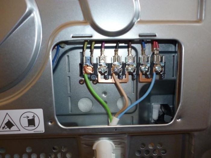
Step 3 - Open the back panel of the stove
To connect the cable to the electric stove, on its back side you need to find and unscrew a small cover that covers the wire terminals.
 Back wall household stove
 Step 4 - Attaching the cable
After you have removed the cover, you need to fix the cable. This is done in order to avoid accidental pulling of the cable from the plate. Insert the cable and fix it on the stove body in a special clamp.
 Hole for wiring ZVI cable
 Step 5 - Installing the Copper Jumpers
Depending on the number of power phases, the wires are connected in different ways. In order to properly coordinate the connection of the plate to various power networks, special copper jumpers are included with the terminal block. According to the scheme you have chosen, install the jumpers in the block and tighten the screws where the wires will not be connected.
 Connecting wires to a household stove
 Step 6 - Connect the Wires
It is very important to correctly connect the wires on the terminal block! In the documentation and often on the case itself, near the cover, there is a connection diagram with various types supply network. According to the diagram that suits your case, connect the wires to the terminals. The color of the wires must match the connection in the plug and socket. The first one connects the ground wire - yellow-green, then the neutral wire - blue. Then phase wires, brown and two black. The main thing here is not to confuse anything so as not to disable the equipment.
 We connect the isolated neutral and ground with a jumper
 Step 7 - Closing the Panel
After connecting all the wires, check the connection diagram again, make sure there are no errors. Tighten the clamping screws well. But remember: in all plates, the connector is made of fragile material, do not use much force, otherwise you may damage it. Now you can close the cover and tighten the mounting bolts.
 Final connection of wires to a household electric stove
 Step 8 - Connecting to the Network
Before connecting the oven to the mains, make sure that the circuit is assembled correctly, all current-carrying parts are closed. Turn on the machine and RCD, check for voltage at the outlet. Plug in the electric stove. According to the instructions, make sure that all its functions work correctly.
Video: video instruction for connecting an electric stove
Connecting the stove in a single-phase network
Unlike a private house or manufacturing enterprise, in the apartment there is no way to connect the electric stove to a three-phase network. Therefore, we will consider a single-phase connection used in apartments. Most stoves have the following wire terminals: L1; L2; L3; N1; N2; and ground contact.
To connect such an electric stove to a 220 V single-phase home network, you must:
- put a jumper between terminals L1 and L2, L2 and L3,
- connect a phase wire to L2 - brown;
- leave a jumper between terminals N1 and N2;
- connect a neutral wire to N2 - blue;
- to the grounding contact marked with a special icon, connect the ground wire - yellow-green.
The number and name of the terminals may differ, specify these data in the documentation for the device.

Single-phase electric stove connection diagram 
A selection of video guides