Automatic temperature control in the greenhouse.
I want to talk about the creation of a simple device that greatly facilitated the life of home inhabitants - automatic regulator gas column temperature. Similar devices have already been created and described here on Habré, I wanted to make a slightly more advanced device and describe in detail the entire creation process from idea and measurement to implementation, without using ready-made modules Arduino type. The device will be assembled breadboard, programming language - C. This is my first development of a complete (and working!) device.
1. Initial data
We live in a rented apartment, which has one very unpleasant property: there is no hot water, cold water is heated on site using a heater (Fluent Gas Water Heater - HSV) located in the kitchen. While taking a shower, if another pressure surge occurs, you have to spank naked to the column or call someone. Integrate a complete smart House» there is no possibility, so it was decided to introduce automatic regulation of the heater. By the way, I quickly found several similar solutions, for example, which means that my problem is known and solved in its own way.VPG model: Vector lux eco 20-3 (China)
Water pressure: about 1.5 kgf / cm² (pressure is low, the heater operates slightly above the allowable limit)
Solution Requirements
- Simplicity
- PID controller or similar
- Possibility to choose the maintained temperature
- Display of current parameters
- Resolving Device Security Issues
System architecture
After some thought, the architecture of the device was sketched out as follows:- Servo drive (directly in the body of the HSV)
- Thermal sensor regular HSV
- Thermal sensor signal amplification unit and servo power supply stabilizer (directly in the body of the HSV)
- Control unit (external)
2. Servo
Since my profession is software engineering and mechanics has always been the most difficult part, I decided to start with it. I must say that I could not get ready for the first stage for a long time, it was very scary to touch the HSV, but another pressure drop forced me to start.Having dismantled the column and looked around, I found places to install the TowerPro MG995 servo, somehow ordered “for delivery” on aliexpress a long time ago.

To eliminate the backlash of the drive rods, I made one rod spring-loaded. The backlash was completely eliminated, but another problem turned out - a servo with a torque > 10 kg * cm turned out to be too bold for the HSV. When turned on, the transients in the electronics of the machine cause a jerk to a random position, and after a couple of idle turns, the rod turned out to be bent! Silumin columns will definitely not withstand such treatment. The geometry of the rocker, which was not on the axis of the regulator, also caused criticism, which led to non-linearity of the adjustment. The final view of the throttle drive assembly:

The unit has been redone - springs from the VAZ were used (from the carburetor - bought at an auto parts store) and the rocker is now on the geometric axis of the shaft. This design has a small backlash, but it is linear in adjustment and can dampen the fury of the steering machine. The corners are set to optimal values for adjustment in the most demanded positions of the regulator.
3. HSV sensor unit
The HSV thermistor changes its resistance within 20..50 KΩ, it is problematic to use it directly as a divider - we get low measurement accuracy. But as it turned out in practice - with an increase in the supply voltage to 12V, you can easily get an acceptable output signal range - just use the op-amp in repeater mode (if necessary, you can change the gain) to isolate the divider from the load. Block diagram inside the HSV:
The divider R2 and the column temperature sensor generate a signal with a voltage of 1.4..4.96 V in the full measurement range (in practice - 20..60 degrees Celsius). Initially, he developed a bridge circuit - which can compensate for the loss of the power source, but was discarded due to the fact that the power source had little effect, and the first point of the "TK" was - "simplicity". The operational amplifier provides decoupling of the divider and the load. The zener diode D1 limits the output voltage to 5.1 V in cases where the sensor is disconnected (otherwise the output would be 12V - which is deadly for the controller) - which will be considered an unconditional error by the controller circuit. The integrated stabilizer 7805 feeds the servo - the solution is unsuccessful, when the machine stops, it heats up terribly and I think it can fail if the drive wedges (if the built-in protection does not work). I will not focus on this block anymore.
4. Controller
The controller is assembled on the basis of the Atmega8 IC in a dip-package.
Clocking - internal oscillator at 8 MHz. Power - another 7805 on the board. Indication via standard LCD1602 display. Block diagram:

The power supply of the unit is controlled from the column through a transistor - using a small-sized relay. The temperature sensor signal (Contact No. 4 of the connector) has a pull-up to ground and when the sensor is disconnected during operation, it will show a very high temperature - which will lead to a decrease in the regulator and will not cause dangerous situations. Assembled block:


4. Testing and adjustment
To test the PID controller, a HSV model was written in Qt. It worked out the main points and situations of the heater operation - cold / hot start, pressure drops. To take the characteristics, a UART connector was added to the controller board, where data on indicators were sent once a second - the current temperature, throttle position, etc.
The tests revealed the following:
- Very large HSV inertia from the beginning of exposure to the reaction on the temperature sensor - about 30 seconds
- Rounding to a degree in the controller firmware is a bad idea, the algorithm could work more accurately
The results of measurement and calibration of the temperature sensor, The dependence can be considered conditionally linear:

The first runs in the program for rendering telemetry from the column:

(I forgot to add a legend to the charts. Here and below - red- sensor temperature, green dotted- throttle position, blue- temperature desired by the user)

Almost a successful adjustment

Good odds options

Good start option
The first runs showed the main parameters of the system, then it was not difficult to measure them and adjust according to the accelerated formula, the parameters were selected for a long and painful time. It was not possible to get rid of fluctuations completely, but fluctuations within 1 degree are considered acceptable. Accepted option:


In the process of selection, the integral coefficient had to be completely turned off, I think that this is due to the large inertia of the system. Final odds:
FloatPk = 0.2; float Ik = 0.0; float Dk = 0.2;
5. Enclosure
The device is assembled in a plastic junction box.
And it works like this.
6. Safety of use
An important question that was asked from the very beginning. Let's go through the main points.Galvanic isolation of column and regulator circuits
What happens if the 12V power supply short-circuits and there is 220 volts on the sensor circuit? This will not cause gas to flow into the column. As it turned out - it will not cause - there are two levels of gas supply in the column - solenoid valve controller and mechanical water valve. It is not enough to open only the solenoid - gas will not flow without water flow.Disconnection or detachment of the sensor inside the HSV
When the thermistor is disconnected from the block inside the VPG, a 0xFF (5.1V) signal will be generated at the output, which is checked by the program as an error, the controller stops the program execution, the servo drive is set to a minimum.Disconnection or detachment of the sensor from the controller
In this case, a high temperature is generated (pulling the sensor line to the ground) which will lead to the output of the drive to the minimum value, which is also safe for the user.Electronic-mechanical protection of HSV
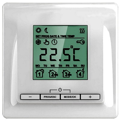
HSV protection prices remain functional in normal mode, in case of boiling / overheating / column draft sensor, standard systems should turn it off.To maintain the required temperature level in heating systems, electrical devices called thermostats are used. All devices with electric heating elements are equipped with electric thermostats.
The need and features of thermostats
The thermostat is electrical device necessary for automatic regulation temperature in the cooling and heating equipment. They are mounted in heating systems, artificial climate, cooling or freezing systems. Widely used in household in the arrangement of greenhouses.
The purpose of the thermostat is determined by turning on or off heating elements any appliance at temperatures below or above those specified, respectively. Due to the operation of thermostatic devices, indoor air, water, instrument surfaces, etc. I have a stable temperature.
All thermostats work, no matter what device they are in, according to a single principle. The automatic regulator receives temperature data from its environment, due to the fact that it is equipped with a built-in or remote temperature sensor. Based on the information received, the thermostat determines when to turn on and off. To avoid malfunctions of the device, the temperature sensor should be installed indoors away from the direct influence of various heating equipment, otherwise, distortion of the indicators may occur and, of course, the controller will work erroneously.
Classification of thermostats
The principle of operation of all devices that regulate the temperature is the same, but there are a lot of types of thermostats, and they differ in:
- Purpose:
room;
weather. - Mounting method:
wall;
wall;
mounted on a DIN rail. - Functionality:
central regulation;
wireless regulation. - Control way:
mechanical;
electromechanical;
digital (electronic).
Also, thermostats differ in technical properties:
- Temperature measurement range. different models thermostats, depending on the modification, maintain a temperature from -60 to 1200 ° C.
- Number of channels:
single-channel. Apply to automatic adjustment and maintaining the temperature of the object at the specified level. Differ in the smaller sizes and weight from multichannel devices;
multichannel. Are issued for fixing of temperature of a series of standard thermal sensors. They are used in factories, laboratories, as well as in the national economy. - Dimensions:
compact;
large;
large.
Application of temperature controllers and sensors
Temperature controllers can be installed in residential and industrial premises. In general, the following can be distinguished:
- And controlling the air temperature in a specific area of the room. These devices are categorized room regulators. There are analog and digital.
- And those that maintain the temperature of certain objects are regulators for underfloor heating.
- Outside air temperature - weather thermostats.
Regulators that are operated in industrial premises are of two types:
- Industrial spatial . These devices include analog wall regulators with increased protection.
- Industrial with separate sensors
. These are analog devices with external sensors that can be wall-mounted or mounted on a special rail.
Sensors can be installed on the walls or in the floor of the house, depending on their type and purpose. Built-in devices are mounted in a mounting box directly into the wall, while surface-mounted devices are simply attached to the wall.
There are also several types of sensors for their intended purpose:
- Floor temperature sensor.
- Air temperature sensor.
- Infrared sensor for floor and air.
A sensor that measures air temperature is often placed on the thermostat housing. Thermostats with infrared sensors can be used to control the entire heating system. These sensors are great for installation in bathrooms, showers, saunas and other environments with high humidity. The temperature controller itself must be placed in a dry place, it can be damaged from an excess of moisture. True, there are models with increased tightness, and their installation in the bathroom is not dangerous for them.
Regulators for underfloor heating differ in their internal structure, these are:
- Digital.
- Analog.
Digital devices have good resistance to different types interference, therefore eliminating data distortion and guaranteeing greater accuracy than analog.
Features of the functionality of electric temperature controllers:
- Wireless regulation (remote) . It is recommended to use for additional installation of heating elements and reconstructions, when it is impossible or rather difficult to perform classical adjustment. Remote control excludes additional construction and repair work during electrical installation (for example, installation of cable wiring).
- Programming devices . The central (classic) device allows you to control the temperature of an entire large object from one point. The controller is programmed using a computer or control devices. Also, control is carried out using a telephone modem.
Principle of operation, pros and cons
Mechanical temperature controller considered a simple and practical device. Used for heating and cooling purposes. Most often represents external wiring product designed for indoor installation in residential premises in heating systems. Appearance similar to a standard stopcock.
Specificity mechanical thermostats is the absence of an electrical component. The device works according to a special principle, which consists in the properties of certain substances and materials to change their mechanical properties from temperature changes.
When the temperature changes to a specifically specified one, a break or short circuit occurs electrical circuit, which causes the heating devices to be turned off or on. The required temperature indicator is selected on the instrument scale by rotating a special wheel.
Positive points of mechanical thermostats:
- Reliability.
- Resistant to voltage drops.
- Not subject to electronic failures.
- Work at negative temperatures.
- Can be used in conditions of sudden temperature changes.
- Simple control.
- Long service life.
Disadvantages:
- The presence of an error.
- The likelihood of small clicks when voltage is applied to infrared heaters.
- Low functionality.
Regardless of the shortcomings, they are the most common and are found in the organization of heating systems more often than other thermostats, due to simple control and low cost.
Operation of electromechanical thermostats
Electromechanical temperature controllers are used in various household electrical appliances. These products come in two versions:

- With bimetallic plate and group of contacts . The plate, heated to a certain temperature, bends and opens the contacts, which stops the supply of electric current to the heating coil or the heating element of the device. After cooling, the plate bends back to its original position, the contacts close, the electricity supply returns and the device heats up. Devices with these regulators are used in Everyday life almost every person is irons, electric stoves, electric kettles, etc.
- With capillary tube. The product consists of a tube filled with gas and placed in a container with water, as well as contacts. The principle of operation is based on the properties of materials to expand at certain temperatures. The substance in the hollow tube begins to expand when the water is heated, which causes the contact to close. After the water cools, the contacts open, and the appliance begins to warm up. Such regulators are most often equipped with water heaters, oil heaters, boilers.
- Automatic inclusion of heating.
- Tightness.
- Low price.
Cons of these devices:
- Low functionality.
- Difficulty in achieving high control accuracy.
The specifics of electronic temperature controllers
Electronic devices are very common, they are operated with many electric heaters. Usually they are equipped with common heating systems and air conditioning, as well as underfloor heating.
Main components:
- Removable temperature sensor.
- The controller is a device that sets a specific temperature level in the house, as well as creating commands to turn the heater on and off.
- Electronic key - contact group.
The instrument's sensor sends temperature data to the controller, which processes the received signal and decides whether to lower or increase the temperature.
Types of electronic thermostats:
- Conventional thermostats . In these devices, you can set the desired temperature limits or the exact temperature that will be stored. The devices are equipped with an electronic display.
- Digital thermostats:
Closed logic. Devices have an unchanged algorithm of operation. Regulation is carried out by sending commands for the specified parameters to specific devices that were installed in advance. The parameters are set in advance depending on the needs of the devices used for a certain temperature. Correction of the program of these controllers is practically impossible, you can only change the main parameters. But it is these thermostats that are most often used in everyday life.
With open logic. These devices control the precise process of space heating. They have advanced settings, so you can change their algorithm of work. Controlled by buttons or touch panel. By means of these devices, it is possible to turn on or turn off heating systems at a strictly specified time. But their reprogramming should be handled by specialists. These regulators are used more often in production and industry than in everyday life.
Programmable thermostats are convenient to operate, they open up ample opportunities for fine-tuning devices to the desired temperature indicators, depending on the requirements of individual areas of the premises.
Advantages:
- Wide range of adjustments.
- Variety of design solutions.
- Saving electricity.
- High accuracy.
- Efficiency.
- Operational safety.
Also, thermostats are easy to manage and have no high cost, only these two pluses do not apply to open logic regulators. Electronic controllers are often integral part smart home systems.
1.
2.
3.
4.
As you know, in order to heat any room with high quality, it is necessary to correctly adjust the temperature indicators so that the heating matches optimally. comfortable conditions and provided a favorable microclimate in the dwelling. Therefore, it is necessary to consider in more detail the features of such a device as a temperature controller for a heating radiator, which is designed to perform all these functions. In addition, you should figure out how to regulate the temperature of the radiator in various buildings, including private and apartment buildings.
The need to install thermostats
Such mechanisms are used for the following purposes:- saving heat produced by heating;
- maintaining a comfortable temperature in the home.

It is very important to remember that during installation it is extremely necessary to have a special jumper located directly in front of the heating device. If it does not exist, then the coolant flow cannot be regulated through the radiator, since this will have to be done through a common riser.
Speaking of savings, this factor is relevant for those owners whose living quarters are equipped with an autonomous heating system, as well as for housing and communal services that use metering devices to pay for heat coming from its producers.
Installation of temperature controllers in apartment buildings
To set the radiator temperature controller to apartment building, it is necessary to understand what constitutes heat accounting in such a design.The supply and return pipelines are equipped with special retaining washers, before and after each of which there are pressure regulating sensors. Due to the fact that the diameter of these sensors is known, it becomes possible to calculate the flow rate of the coolant circulating through the sensors. As a result, the difference obtained between the water flow in the supply and return pipelines will reflect the amount of water used by the residents.

Temperature sensors are designed to control both areas. Therefore, knowing how much heat is consumed and what its temperature is, you can easily calculate the amount of heat that remains in the room.
In order to regulate the operation of heating was easier, you need to constantly monitor the state of the temperature.
This can be done in one of two ways:
- Mounting shut-off valve . Such a device is designed to partially shut off the pipeline system if the return temperature is higher than the set one. It is a conventional solenoid valve. This option will be suitable for those houses where the heating system is relatively simple and does not have a large volume of coolant.
- Valve device three way type . This device also allows you to adjust the current flow rate of the coolant, but it functions a little differently: in the event that the water temperature exceeds the norm, then it is sent through open valve into the supply pipeline more. By mixing with cooled water, the overall temperature will decrease, while the required circulation rate will be maintained.

Installation of mechanical regulators is not particularly difficult. To install such a device, you only need to connect it to the flange in the elevator assembly. It is also important that the price of such devices is much lower compared to electronic mechanisms.
Installation of temperature controllers in private homes
As a rule, an automatic heating temperature controller is an integral part of a heating boiler in autonomous system heating. Such a sensor can be mobile, that is, it can be carried, and is also capable of measuring the temperature in the room.Electric boilers use electronic sensors, which are directly connected with the installed heating elements (thermal electric heating elements) or with the voltage that occurs on the electrodes or on the boiler winding.
Boiler systems operating both with gas and pyrolysis technology are often equipped with mechanical regulators, the main advantage of which is independence in terms of energy. But this option, of course, does not imply the use of remote temperature sensors. See also: "".

Temperature sensors for radiators
Sometimes one temperature sensor carries several heating radiators. First of all, the installation scheme affects this. But it is much more common to mount the regulator on each heating device separately.
Many owners install a system familiar to many, called "Leningrad", the principle of which is to use one pipe encircling a house or one floor, which has a rather impressive diameter, and radiators or convectors are built in parallel with it.
It is worth noting that in order to adjust the heating temperature, you can use not only standard devices.
Common mechanisms of this type include:
- thermostatic head. Represents automatic sensor, which controls the temperature of the coolant in the battery. The principle of its operation is as follows: in the process of heating, liquid and gaseous substances expand (details: ""). This, as a consequence, leads to the fact that the heated product squeezes out a special rod, thereby blocking the access of the coolant;
- devices called chokes are no less often used. They are special taps. screw type, with which you can adjust the permeability of the coolant manually. Their cost is more affordable, and in addition, they can be used to control two-pipe heating systems;
- The least expensive and simplest mechanism to help regulate temperature is the traditional valve. Of course, in this case, you should only use modern models, and not outdated screw devices, since valves are very often torn off in old mechanisms, and there is also a risk of oil seals leaking. The situation is completely different with ball valves: even in the half-open position, they function reliably and efficiently over a long period of time.
In order for the device of temperature controllers to be as convenient as possible, many experts recommend that you first study various photos these devices and detailed videos on their correct connection.
An example of heating temperature controllers on video:
Temperature is an indicator of the thermodynamic state of an object and is used as an output coordinate in the automation of thermal processes. Characteristics of objects in temperature control systems depend on the physical parameters of the process and the design of the apparatus. So general recommendations it is impossible to formulate temperatures for the choice of ACP and a careful analysis of the characteristics of each specific process is required.
Temperature control in engineering systems ah is performed much more often than the regulation of any other parameters. Range controlled temperatures small. lower limit this range is limited minimum value outside air temperature (-40 °C), upper - maximum temperature coolant (+150 °С).
To common features ACP temperature can be attributed to the significant inertia of thermal processes and temperature meters (sensors). Therefore, one of the main tasks in creating a temperature ACP is to reduce the inertia of the sensors.
Consider, as an example, the characteristics of the most common manometric thermometer in engineering systems in a protective case (Fig. 5.1). block diagram such a thermometer can be represented as a series connection of four thermal containers (Fig. 5.2): a protective cover /, air gap 2 , walls of the thermometer 3 and working fluid 4. If we neglect the thermal resistance of each layer, then the heat balance equation for each element of this device can be written as
G,Cpit, = a n? sjі ( tj _і - tj) - a i2 S i2 (tj -Сн), (5.1)
where Gj- the mass of the cover, air layer, wall and liquid, respectively; Cpj- specific heat capacity; tj- temperature; a,i, and /2 - heat transfer coefficients; S n , S i2 - heat transfer surfaces.
Rice. 5.1. circuit diagram manometric thermometer:
- 1 - protective cover; 2 - air gap; 3 - thermometer wall;
- 4 - working fluid

Rice. 5.2.
As can be seen from equation (5.1), the main directions for reducing the inertia of temperature sensors are;
- increase in heat transfer coefficients from the medium to the cover as a result right choice sensor installation locations; in this case, the velocity of the medium must be maximum; ceteris paribus, it is more preferable to install thermometers in the liquid phase (compared to gaseous), in condensing vapor (compared to condensate), etc.;
- reduction of thermal resistance and thermal capacity of the protective cover as a result of the choice of its material and thickness;
- reduction of the time constant of the air gap due to the use of fillers (liquid, metal chips); for thermocouples, the working junction is soldered to the body of the protective cover;
- selection of the type of primary converter: for example, when choosing, it must be taken into account that a thermocouple in a fast-response design has the smallest inertia, and a manometric thermometer has the largest.
Each temperature ACP in engineering systems is created for a very specific purpose (controlling the temperature of the air in the premises, heat or coolant) and, therefore, is designed to operate in a very small range. In this regard, the conditions for the use of one or another ACP determine the device and design of both the sensor and the temperature controller. For example, in the automation of engineering systems, direct-acting temperature controllers with manometric measuring devices are widely used. So, to regulate the air temperature in the premises of administrative and public buildings when using ejection and fan coils of a three-pipe heating and cooling circuit, a direct-acting regulator is used direct type RTK (Fig. 5.3), which consists of a thermal system and a control valve. The thermal system, which proportionally moves the control valve stem when the temperature of the recirculation air changes at the inlet to the closer, includes a sensitive element, a setting device and an actuator. These three nodes are connected by a capillary tube and represent a single hermetic volume filled with a temperature-sensitive (working) liquid. A three-way control valve controls the supply of hot or cold water to the ejection heat exchanger

Rice. 5.3.
a - regulator; b - control valve; c - thermal system;
- 1 - bellows; 2 - setter; 3 - tuning knob; 4 - frame;
- 5, 6 - regulating bodies respectively hot and cold water; 7 - stock; 8 - actuating mechanism; 9 - sensing element
closer and consists of a body and regulatory bodies. With an increase in air temperature, the working fluid of the thermal system increases its volume and the valve bellows moves the stem and the regulating body, closing the passage of hot water through the valve. With an increase in temperature by 0.5-1 ° C, the regulatory bodies remain motionless (hot and cold water passages are closed), and with more high temperature only the cold water passage opens (the hot water passage remains closed). The set temperature is provided by turning the adjustment knob connected to the bellows, which changes the internal volume of the thermal system. The controller can be set to temperatures ranging from 15 to 30°C.
When controlling the temperature in water and steam heaters and coolers, RT type regulators are used, which differ slightly from RTK type regulators. Their main feature is the combined design of the thermocylinder with the adjuster, as well as the use of a two-seated valve as a regulating body. Such gauge regulators are available in several 40-degree ranges ranging from 20 to 180 °C with nominal diameters from 15 to 80 mm. Due to the presence of a large static error (10 °C) in these controllers, they are not recommended for high-precision temperature control.
Manometric thermosystems are also used in pneumatic P-regulators, which are widely used to control temperature in engineering air conditioning and ventilation systems (Fig. 5.4). Here, when the temperature changes, the pressure in the thermal system changes, which acts through the bellows on the levers that transmit force to the pneumatic relay rod and the membrane. When the current temperature is equal to the set one, the entire system is in equilibrium, both valves of the pneumatic relay, supply and bleed, are closed. When the pressure on the stem increases, the supply valve begins to open. It is supplied with pressure from the mains. compressed air, as a result of which a control pressure is formed in the pneumatic relay, increasing from 0.2 to 1 kgf / cm 2 in proportion to the increase in the temperature of the controlled medium. This pressure activates the actuator.
For automatic control of air temperature in rooms, thermostatic valves of the American company began to be widely used. Honeywell and radiator thermostats (thermostats) RTD, issued by the Moscow branch

Rice. 5.4.
with manometric thermosystem:
- 1 - pneumatic relay rod; 2 - node of unevenness; 3, 9 - levers;
- 4, 7 - screws; 5 - scale; 6 - screw; 8 - spring; 10 - bellows;
- 11 - membrane; 12 - pneumatic relay; 13 - thermal bulb; 14 - feeding
valve; 15 - bleed valve
Danish company Danfoss, the required temperature is set by turning the adjusted handle (head) with a pointer from 6 to 26 °C. Lowering the temperature by 1 °C (for example, from 23 to 22 °C) saves 5-7% of the heat consumed for heating. thermostats RTD allow avoiding overheating of the premises during the transitional and other periods of the year and provide a minimum required level heating in rooms with periodic residence of people. In addition, radiator thermostats RTD provide hydraulic stability for a two-pipe heating system and the possibility of adjusting and linking it in case of errors during installation and design without using throttle washers and other constructive solutions.
The temperature regulator consists of a control valve (body) and a thermostatic element with a bellows (head). The body and head are connected with a threaded union nut. For ease of installation on the pipeline and connection of the thermostat to the heater, it is equipped with a union nut with a threaded nipple. The room temperature is maintained by changing the water flow through heater(radiator or convector). The change in water flow occurs due to the movement of the valve stem by a bellows filled with a special mixture of gases that change their volume even with a slight change in the temperature of the air surrounding the bellows. The elongation of the bellows with increasing temperature is counteracted by a setting spring, the force of which is adjusted by turning the handle with an indicator of the desired temperature value.
To better suit any heating system, two types of regulator housings are available: RTD-G with low resistance for single pipe systems and RTD-N with high resistance two-pipe systems. Bodies are manufactured for straight and angle valves.
Thermostatic elements of regulators are manufactured in five versions: with built-in sensor; with remote sensor (capillary tube length 2 m); with protection against misuse and theft; with setting range limited to 21 °С. In any version, the thermostatic element ensures that the set temperature range is limited or fixed at the required room temperature.
Service life of regulators RTD 20-25 years, although the Rossiya Hotel (Moscow) registered a service life of 2000 regulators for more than 30 years.
Control device (weather compensator) ECL(Fig. 5.5) ensures the maintenance of the temperature of the coolant in the supply and return pipelines of the heating system, depending on the outdoor temperature according to the corresponding specific repair and a specific heating schedule object. The device acts on the motorized control valve (if necessary, also on circulation pump) and allows you to perform the following operations:
- maintenance of the calculated heating schedule;
- night drop temperature graph by weekly (interval 2 h) or 24-hour (interval 15 min) programmable clock (in the case of an electronic clock, the interval is 1 min);
- heating of the room within 1 hour after the night temperature decrease;
- connection via relay outputs of a control valve and a pump (or 2 control valves and 2 pumps);

Rice. 5.5. Weather compensator EC/. with setting,
available to the consumer:
1 - programmable clock with the ability to set operating periods for comfort or reduced temperature on a daily or weekly cycle: 2 - parallel movement of the temperature graph in the heating system depending on the outside temperature (heating graph): 3 - operating mode switch; 4 - a place for the instruction manual: 5 - signaling the inclusion, the current mode of operation,
emergency modes;
O - heating is turned off, the temperature is maintained to prevent freezing of the coolant in the heating system;) - operation with a reduced temperature in the heating system; © - automatic switching from mode comfortable temperature to the low temperature mode and back in accordance with the setting on the programmable clock;
O - work without lowering the temperature on a daily or weekly cycle; - manual control: the regulator is off, the circulation pump is always on, the valve is controlled manually
- automatic transition from summer mode in winter and back according to the set outdoor temperature;
- termination of the night temperature decrease when the outside temperatures fall below the set value;
- protection of the system from freezing;
- correction of the heating schedule according to the air temperature in the room;
- switching to manual control of the valve drive;
- maximum and minimum supply water temperature limits and the possibility of fixed or proportional
temperature limitation return water depending on the outdoor temperature;
- self-testing and digital indication of temperature values of all sensors and states of valves and pumps;
- setting the dead zone, proportional band and accumulation time;
- the ability to work on the accumulated over a given period or current temperature values;
- setting the coefficient of thermal stability of the building and setting the influence of the return water temperature deviation on the supply water temperature;
- protection against scale formation when working with gas boiler. In engineering systems automation schemes,
also bimetallic and dilatometric thermostats, in particular electric on-off and pneumatic proportional.
The electric bimetal sensor is mainly intended for on-off temperature control in rooms. The sensitive element of this device is a bimetallic spiral, one end of which is fixed, and the other is free and satisfies moving contacts, closing or opening with a fixed contact, depending on the current and set temperature values. The desired temperature is set by turning the setting dial. Depending on the setting range, the temperature controllers are available in 16 modifications with a total setting range from -30 to + 35 °C, with each controller having a range of 10, 20 and 30 °C. Operation error ±1 °С at the middle mark and up to ±2.5 °С at the extreme marks of the scale.
The pneumatic bimetallic regulator as a transducer-amplifier has a shutter nozzle, which is acted upon by the force of the bimetallic measuring element. These regulators are available in 8 modifications, direct and reverse action with a total setting range from +5 to +30 °C. The setting range of each modification is 10 °C.
Dilatometric regulators are based on the difference in the coefficients of linear expansion of an invar (iron-nickel alloy) rod and a brass or steel tube. These thermostats do not differ in the principle of operation of control devices from similar regulators using a manometric measuring system.
Every gardener or gardener dreams of having a greenhouse on his plot. A greenhouse is a kind of resort area where plants feel good regardless of weather conditions. And how pleasant and useful it is to get a crop of lettuce, radish in early spring when an ordinary liverwort appears on the newly appeared thawed patches!
Naturally, in order to obtain such results, it is necessary not only to construct good greenhouse but also to support there optimal temperature. Air and soil temperature is important.
These factors affect absorbency useful elements, moisture; qualitative and quantitative indicators of the harvest; occurrence of various diseases.
Any gardener should understand that there is a direct relationship between the temperature of the air, the soil inside the greenhouse, and the possible harvest. However, many neighboring cultures like different modes of humidity and temperature. By optimizing the placement of crops in the greenhouse, you can take advantage of the significant temperature difference in its various parts.

In the greenhouse, as well as in the unprotected ground, there are daily temperature fluctuations. Too sharp, exceeding 4 - 8 ° C, drops negatively affect the growth, development of plants, productivity. Lead to frequent diseases and death of crops. Depending on the type of plant, the temperature of the soil and air in the greenhouse should be at around 14 - 25 ° C.