What is the temperature of the exhaust manifold of the car. Back pressure measurement. System design and pipe size
If you are not an expert, then you probably do not know about all the temperature processes under the hood. But we will eliminate this flaw and tell you why you need thermal tape for the exhaust manifold.
Choosing how to wrap the exhaust manifold - types and functions of materials
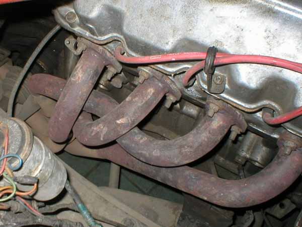
As is known from the course of physics, the volume of gas is directly proportional to temperature, that is, the higher the latter, the greater the first parameter will be. It follows from this that the heated ones will exit the car engine much faster. But in the engine compartment, the air does not heat up above a hundred degrees, while the temperature of the car's exhaust manifold is more than a thousand.
So please, if your car ever catches fire, just get out. Someone nearby will be able to call emergency services. Thank you to all our customers for your support and trust in meeting your vehicle's needs. Until next time, Terry and the crew wish you all the best!
Heat is the number one killer for all vehicle components, especially electronics and moving parts. There is a giant heat generating engine under the hood of your car, so reducing radiant heat under the hood not only helps required components last longer, it also helps improve your engine's performance. The cooler the air charge entering the engine, the denser it is, which means more potential energy.
And again, returning to physics and the laws of heat transfer, it can be argued that gases are cooled due to such a low temperature of the engine compartment, which means that the process of their release slows down. Thermal tape can solve all these problems by creating excellent thermal insulation of the collector, it will keep heat in and at the same time will not allow the engine to overheat from the heat that is released from the exhaust.
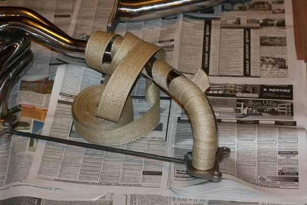
One of better ways to reduce heat under the hood is an exhaust heat wrap. Exhaust heat wrap insulates your exhaust manifolds, keeping heat inside exhaust gases, where it travels much faster, and reduces radiant heat that kills components and heats up the incoming air charge for the engine. This is done according to two principles: the first is isolation. Like a coat, a wrap contains heat inside the tubes. By using a fiberglass base along with proprietary materials, exhaust wraps can reduce time rates by as much as 50%.

There are three main types of such tapes on the automotive market, differing in composition and color. The most common among car owners are black and white thermal tapes. In principle, they are at the same consumer level and are identical in their properties. . Bronze is considered more effective, its thermal insulation properties are better than those of previous options by as much as 30%, and all thanks to a different composition..
Considering that for each degree of temperature drop, engine performance can increase by 1%, this is a serious potential increase in performance. The second principle is the thermodynamics of gases. Hot gases move much faster than cold gases. The wrapped exhaust traps heat within the exhaust gases by keeping the gases heated further down the pipe. This makes things move faster, which actually helps get more fuel and air into the combustion chamber for the next charge. This is called scavenging, and increasing this value always results in more power.
Exhaust manifold insulation - when to act?
The design of the exhaust manifolds provides for the presence of a steel screen, which also acts as thermal insulation. If, as a result of tuning or for some other reason, there is none, then you can not do without thermal tape. The collector temperature, as mentioned above, can reach as much as 1600 ° C, while after the engine stops, it cools down quite quickly. Thus, condensation forms in it.
Installing the wrap is the hardest part, especially in tight turns. There are a few tricks to make this easier, as we've illustrated below. We took a set of custom headers and a turbo pipe to show you the exhaust pipe installation process. After you do the first part, the next one is much easier.
Most exhaust gases are attenuated slightly by water. You can use a syringe bottle or simply soak the wrapper in water and squeeze out the excess. This helps wrap the stick around for yourself a little better. When it dries, the wrap will hold its shape a little better.
This phenomenon is especially dangerous during the cold season, as the droplets will solidify and interfere with the exhaust gases, which can cause poor starting of the engine.
Large simple pipes simple, but when it comes to headlines; you need an extra set of hands to complete the challenge. The tight curves and intersecting pipes make the headers quite tricky, a second set of arms help hold the headers while you pull and stretch the wrap around the pipes.
Another issue with headers is pipe intersections. You can't wrap a header or collective with a single wrapper, you need to wrap each smaller tube and then wrap the larger tube to include a wrap over the smaller tubes. tape holds protective film until you complete the wrapper. Remove the tape right in front of the joint wrap.
To understand that thermal insulation of the exhaust manifold is urgently needed, the following signs will help. First of all, your "iron horse" will lose power, and problems with starting the engine are also possible, especially when the car stalls. Sometimes there are even cases when black smoke comes out of the exhaust pipe. In addition, a special light will come on on the instrument panel in the cabin, signaling an overheating of the motor.
The exhaust wrap is secured with stainless steel ties, they are not cheap and are not removable. The first heading is often good practice for the second, where you can find best method. For this reason, we suggest that you do not provide links to the first part until after you have completed the second heading, you may decide to move the first.
The exhaust port adds thickness to the pipes, so in vehicles with really tight gaps, you can check the fit before attaching the zip ties. We have found that repackaging is sometimes required to obtain proper clearance.
Thermal tape for the exhaust manifold - how to use it correctly?
In order not to bring your car to such a critical state, you need to think in advance how to wrap the exhaust manifold. There are not so many options, in principle, you just need to choose the right thermal tape. They differ in composition, color, manufacturers and operating temperature, the latter can vary from one to two thousand degrees.
This gives a lot of coverage and minimizes buildup. When you reach the end of the pipe, roll up the wrap to remove the worn edges. If you follow these steps and get some patience, your exhaust gas job will last a long time and help keep those bottom rates going. Don't forget to secure the wrap with stainless steel pegs once you're satisfied with the results.
S. and ended two weeks later in Tacoma, Washington. Obviously, this is not a muscle machine, but our experience with it illustrates our point. The article continues after the advertisement. For the entire length of the race, ambient temperatures were in the high 90s, cracking into the 100s. Our onboard thermometer told us that the temperature on the floor of the truck was 130 degrees. The temperature was even higher when the exhaust pipe was closest to the floor. For 100 miles, the heat on the floor burns your feet through a pair of heavy boots.
Exhaust system and exhaust manifolds
Your ideas about how the engine internal combustion produces power, will become more accurate with the study of the dynamics of the movement of gases. This is more than true for the exhaust system. Although many of the "moving" parts in this system do not require lubrication or periodic maintenance, they nevertheless experience significant dynamic loads. In a space bounded by thin steel, there is a place where gases with a temperature of more than 1100 ° C and under pressure move at the speed of sound, interact with environment either to help the engine in the release of its cylinders from exhaust gases, or to counteract this process. This chapter will help you look inside the exhaust system and show you easy ways to increase power by reducing drag and increasing exhaust tract scavenging. You will also learn about some special technologies, which can be used to optimize exhaust flow and increase power.The exhaust system reduces noise. Silencers used for this act like a cork. The best mufflers for uprated engines aren't precisely stamped, finely tuned, and high-tech mufflers. The best mufflers are simply no mufflers!
It's so hot, so long, that our co-driver Janet Thompson experienced heat exhaustion and dehydration after six days in the cabin. The engine in your car that is exposed to high temperatures can experience similar problems. Heat robs you of engine performance and causes premature failure of internal engine components. Not only that, proper heat management can make your muscle car's cabin a lot more comfortable during the summer months. There are several things you can do to make your engine run cooler. hot weather which will improve performance and fuel efficiency.
If the exhaust system were just a bunch of pipes that direct the flow of exhaust gases towards the rear of the car, then the job of optimizing the system would be relatively simple. However, the exhaust system is designed to perform at least one additional task: it must reduce engine noise. These non-boost requirements lead to the use of mufflers, and mufflers make it much more difficult to get maximum power. Camshafts can be refinished to full profile, cylinder heads can be bored, carburetors can be fine tuned, and all of these modifications can improve power. And the best mufflers are not those that are finely optimized, fine tuned, or high tech designs. The best mufflers are no mufflers!
Exhaust system and exhaust manifolds
Your engine is one big thermal converter. Air and fuel are burned to create heat, which is converted into energy. This leaves 70 percent of that heat without a place, and its tendency is to sit there in the engine bay. As your engine produces more power, it creates more heat. As heat rises, there is a limit to how much can be removed by movement. vehicle cutting through Fresh air. The fan is designed to draw air from the outside of the grate to aid cooling, but it doesn't always pull enough air to offset the heat generated by the combustion process, especially if outdoor air the one you draw in is already hot.
Back pressure and power
Silencers work like a cork. They create resistance to the flow of gases, increase the back pressure in the exhaust system, and as a result of this, noise is partially reduced. Although noise reduction is pleasant to the ear, it degrades engine power and fuel economy.Reducing exhaust back pressure will always improve power and fuel economy, provided the air/fuel ratio and ignition timing are carefully optimized, and back pressure is increased before and after the exhaust system. If you reduce the back pressure in the exhaust system and optimize the engine for these conditions, then in 999 cases out of 1000 you will find an increase in power.
Adding extras and extras under the hood on newer vehicles also exacerbates the engine cooling process. All that extra heat has to go somewhere, and your ability to dissipate heat is limited by the cooling system. exhaust pipes or standard radiant heat that wakes up metal surfaces such as block, cylinder heads and manifolds. Helping to reduce or manage this heat in one of several ways will improve the performance of your engine and reduce wear and tear on your transmission and your starting and electrical systems.
Computer controlled motors
Many late model cars use sophisticated engine control computers that analyze some engine parameters and instruct the ignition system several times per second how to advance and retard the ignition timing and/or control the fuel injection nozzles to change the amount of fuel entering the air stream. Needless to say, this complex system must be carefully tuned by engineers well trained in both engine and computer engineering. There is nothing surprising in the fact that an arbitrary change in any part of this complex system can lead to unexpected changes, the result of which is a deterioration in throttle response and a decrease in engine power.Under these conditions, installing a low back pressure exhaust system without other modifications may not improve engine performance. If the vehicle is to be used for cross-country or racing purposes and more power is desired, there are three possibilities:
Benefits of Using Exhaust Manifolds
Storing both fuel and air cooler will promote combustion. In a nutshell, a colder engine will produce more power and waste less energy. There are a few things to think about when it comes to heat management. Of course, part of the equation lowers the temperature of the engine. But you'll also want to figure out how to keep residual heat from damaging other components under the hood and getting into the passenger cabin. First of all, let's look at your car's cooling system.
You can replace the standard memory block with a boosted version. These blocks are electronic circuits that contain instructions for operating a computer. New blocks can improve power, but without constant contact with the electronics manufacturer, tuning will be very difficult and usually somewhat similar to the well-known trial and error method.
Great freedom customization can be obtained by installing a prefabricated computer system. These additional blocks "intercept" information going to and from the standard computer. By turning some of the adjusting resistors that are located on the circuit blocks with a screwdriver, the user can change the characteristics of the ignition system and fuel system.
The last and most direct way to "come with" the engine management system is to remove it entirely and install more conventional conventional ignition and carburation (or fuel injection) systems. When engine systems can be freely recalibrated, the benefits of a low back pressure exhaust system will be fully realized.
Back pressure measurement
In simple terms, a high performance engine can be defined as an engine that produces more exhaust than a standard engine of the same displacement. Since engine power is obtained from fuel combustion, the more fuel that is efficiently burned in the engine, the more power (and the amount of exhaust gases it will produce). Therefore, every engine modification that improves power will increase back pressure unless the necessary changes are made to the exhaust system. In fact, a 40% increase in power will typically double the back pressure, and if you expect to double the engine power, the back pressure will quadruple.But do not rush to immediately throw away your mufflers and exhaust pipes. First you must measure how much back pressure is developing in your exhaust system. Fortunately, this task does not require expensive diagnostic equipment. All you need is a pressure gauge, some connectors and tubing. The manometer must be designed to measure pressure of the order of 0.7 kgf / cm3; in extreme cases, you can use a pressure gauge to measure fuel pressure. It is best to have a pressure gauge with a large scale for easy measurements. Weld a piece of "thread" into the exhaust system in front of the mufflers, and if the car is equipped with a catalyst, then add a thread in front of it. The thread can be a simple hex nut threaded to accept 3.2mm or 6.3mm tubing. Due to the high temperatures in the system, connecting a pressure gauge to the threaded port requires additional work. Drill a small hole through the exhaust pipe plug (this plug should have the same thread size as the welded nut) and braze a piece of 300-450 mm long, 3.2 mm (1/8 inch) inner diameter steel tube with high temperature solder, which often used as a brake tube, drilled into the hole. The steel tube will dissipate excess heat from the hot exhaust system so you can connect rubber hose going to the manometer. Make sure that the hose does not touch other hot parts of the exhaust system. After measuring the back pressure, you can remove the tube and plug the exhaust system with a threaded plug without a tube hole.
Many aftermarket radiator manufacturers have developed new technology cooling for their replacement heatsinks, making them more efficient than original hardware designs. In these days of miniaturization, manufacturers have found that doubling the number of fins per inch in a heatsink core allows them to build heatsinks with shorter fins. This allows them to incorporate the cooling capacity of a three-row radiator into the same space as the original two-row radiator core.
Back pressure and power
Some radiator specialists build race-ready radiators for various applications in muscle cars. Eric Christie from Richmond, Texas where they know a thing or two of which has been about heat management. The pace remained at 170. While he was sitting in motion in the light, the pace went up to 180 or 185 degrees,” Christy said. Previously, the car ran 200 degrees on the highway. In motion, it heats up to 220, sometimes a little higher. This design means that when the engine is idling, the more fan blades "dig" into the surrounding air, resulting in cooler ventilation into the engine bay.
Back pressure is measured when the vehicle is accelerating at wide open throttle. With a regular increase in speed, determine the pressure values \u200b\u200bon the pressure gauge. Any back pressure is undesirable, but it must be approached practically. Since it is impossible to achieve zero resistance to flow, it is necessary to achieve realistic goals. The resulting back pressure graphs illustrate that a standard exhaust system can generate pressures up to 0.6 kgf/cm2 (and even more on some conventional vehicles). With careful selection of mufflers, catalysts and exhaust pipes, the same engine will develop a back pressure of no more than 0.15 kgf / cm 2. If, during measurements, back pressure values \u200b\u200bof more than 0.35 kgf / cm 2 are obtained when working with a fully open throttle valve in any speed range, then the exhaust system needs to be improved.
At higher RPMs, the blades align to provide less cooling, but since the car is theoretically moving through the air faster, the fan action is somewhat redundant. Also, with the added mass of the stock fan, engine parts work harder than they actually do at high RPMs. Additional cooling capacity can be realized by installing a pusher fan. They are available in various sizes and are thermostatically controlled. This can often be good after the engine is turned off.


Checking the back pressure in the exhaust system. 1 - pressure gauge; 2 - catalyst; 3 - to check the back pressure of the catalyst, weld a threaded nut into the system here; 4 - to check the back pressure of only the muffler, weld a threaded nut into the system here; 5 - muffler.
The tappets mount to the front of the radiator and assist your stock blade in pumping fresh cold air to the front of the engine. This is because they are driven by their own electric motor instead of mechanical power from the engine's pulley system. And aftermarket electric fan modules come with their own fan shroud and mounting hardware for easy installation. The use of an original or aftermarket fan shroud is another factor in ensuring sufficient outside air.
Catalysts
To reduce the content of hydrocarbons (CH or HC), carbon monoxide (CO) and oxides of nitrogen (NO X) in the exhaust gases, most of the latest models of cars use a catalyst in the exhaust system. This device looks like a silencer but uses precious metals such as platinum, palladium and rhodium to do its job. They enter into chemical reactions with toxic substances, changing the composition of exhaust gases so that CO, CH and NO X are converted into CO 2 (carbon dioxide), H 2 O (water) and N 2 (nitrogen). In fact, the catalyst is so effective at reducing pollutant concentrations that most other emission control devices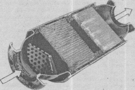
A shroud should be used whenever possible. The cloaker collects the incoming air and directs it in the direction where it will do its best, mainly for the fan and towards the front of the unit. When the engine's operating temperature reaches approximately 220 degrees, the intake air is warm enough to atomize the fuel mixture and the engine is running at maximum efficiency. Manufacturers have learned that increasing pressure in the cooling system will also raise the boiling point of the engine coolant.
The boiling point of water rises approximately 3 degrees for every additional pound of pressure that the radiator cap is rated for. This is why, although water boils up to 212 degrees, most temperature gauges don't indicate that you're in danger of boiling up to 240 degrees. In fact, with newer "closed" cooling systems using a recovery tank, temperatures in the 245 to 265 degree range are generally considered optimal for normal driving. If your vehicle was not originally equipped with a refrigerant recovery tank, installation additional equipment for the secondary market worth the investment.
Catalyst device
on modern cars, they are used only for fine-tuning combustion processes and optimizing the operation of the catalyst.
Catalyst Disadvantages
In most cases, the catalyst has more flow resistance than the muffler. This is especially true for catalysts from General Motors and Chrysler. Most Ford catalysts, however, use a honeycomb design that flows better than other designs. However, thanks to advances in exhaust gas control systems, several new types of catalysts have been created and are being developed. Some of the newer designs are called two- or three-way catalysts, and they use air injection into them to help with the exhaust gas control process.Due to the variety of designs and the close integration of catalysts with other engine systems, it is not possible to make specific recommendations for increasing power while maintaining a low level of toxicity.
Catalyst modifications
There is a wide variety of flow potentials between different catalysts. The main reasons for this are related to the main design. The least efficient catalysts often use balls of active substances, which, fortunately, are becoming less popular. Catalysts of this type pass the flow of exhaust gases through a plurality of balls coated with active substances, which creates a noticeable resistance to the flow. On the other hand, Ford catalysts (used by others) have a honeycomb structure. While this may appear to be a highly resistive design, such a catalyst is quite effective. The greatest resistance in most honeycomb catalysts is at the inlet to the honeycomb structure. By means of altered inlet and altered outlet designs, it is possible to remarkably improve the flow through such catalysts. Bench tests have shown an improvement in flow of approximately 8.51 M3/min (at 635 mmH2O). This equates to a 250% improvement in flow over a typical industrial catalyst.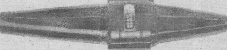
The new extended inlet and outlet for the honeycomb catalyst can significantly increase flow volume.
Experiments with industrial catalysts have confirmed their main drawback: they are expensive!
Hot! And keep it that way
Catalysts work properly when they are hot, even red-hot! At temperatures of 200-260°C, the catalyst reaches an initial temperature at which the efficiency of converting toxic substances into harmless compounds is about 50%. The operating temperature for complete conversion is from 500 to 900°C, i.e. close to the temperature in the combustion chamber. Steel at these temperatures is red-hot.These temperatures must be taken into account when working with catalysts. First of all, the catalysts only reach such high temperatures if they are located very close to the exhaust manifold openings. The temperature of the exhaust gases may drop noticeably as early as 1.0-1.2 m from the exhaust manifold and the catalyst may not even reach the initial operating temperature. Secondly, high temperatures catalytic converters require adequate thermal insulation to prevent heating and ignition of parts on the bottom of the body and next to the catalyst. This can happen when the car is stopped after intensive work, when the catalytic converter remains hot for a long time after the car has stopped.
There are several factors that can affect the life of the catalyst, especially when it is running on a boosted engine. If you follow the instructions below, the catalyst will serve for a long time and without fail:
Do not use leaded gasoline with a catalytic converter installed on the engine. Lead will deposit on the catalyst material and interfere with its performance. However, if you accidentally refuel with leaded gasoline and it is low in lead, the deposited lead may be burned off the catalyst and the catalyst will start working properly again.
Keep the air/fuel mixture ratio as close to stoichiometric as possible (approximately 14.7:1) as toxic gas emissions are minimal with this mixture composition and this prevents excessive catalyst temperatures.
Keep the engine in good condition; misfiring, sticking choke, "dieseling" (running the engine with the ignition off) or "pouring" the carburetor lead to fuel entering the catalyst, which leads to its combustion inside the catalyst, i.e., an increase in catalyst temperature and a reduction in service life.

Catalysts must be located very close to the exhaust manifold openings in order to achieve an initial temperature of 200 to 260°C. 1 -150°C; 2 - 260°C.
Silencers
After the catalyst, the next big obstacle to the flow of gases is the muffler. A well-designed muffler will reduce engine noise without creating excessive back pressure or "suffocating" the engine. Unfortunately, not all mufflers are well designed. In fact, some mufflers are so "good" at creating back pressure that they can take 30 to 40 horsepower. with. on a factory-boosted V8 engine. But at the same time, there are also perfectly working mufflers, and by choosing the right muffler design, you can get a significant increase in power.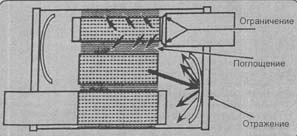
Silencers reduce noise in three ways: by limiting, absorbing, and reflecting.
Silencers can be divided into three main categories: restrictors, absorbers, and reflectors. The "silence" of most industrial mufflers is achieved by restricting the flow, which is done by forcing the exhaust gases through small diameter channels. Unfortunately, this technique also creates a lot of back pressure and draws a lot of power. Special mufflers, on the other hand, are often based on absorption, where the sound entering the enclosure is converted into heat as it interacts with an absorbent material like fiberglass through a friction process. This method creates less back pressure, but is less effective at dampening noise. Silencers also use internal partitions to reflect sound waves back to the input side. The best mufflers for uprated engines often combine reflection and absorption techniques to improve sound attenuation properties while maintaining large internal channels to reduce gas flow resistance. An excellent example of such designs is the CYCLONE SONIC TURBO muffler. It uses insulating glass absorption and reverse acoustic "mirrors" to reflect sound waves.
Image "Turbo"
During the last 20 years, some mufflers with a "Turbo" reputation have become popular for use in uprated engines. The first "turbo" muffler was developed in the USA for the turbocharged engine used in the CHEVROLET CORVAIR in the 1960s. It used a combination of reflection and absorption systems and was designed to reduce the already low noise from the turbocharged engine (turbochargers reduce exhaust noise substantially). Since very strong noise reduction is not required, the muffler back pressure was quite low. Designers of hot rod cars soon began to believe that it could be used in this area, although its dampening properties on normal naturally aspirated engines were rather limited. Responding to market demands, some manufacturers have used this "turbo muffler" image to increase sales. The mufflers that many sold due to their technical "similarity" to the original design were not always bad and some of them could well be installed on uprated engines. In fact, some turbo designs have been proven to have more drag than stock mufflers.ceramic blocks
IF there was a product sold and bought with suspicion, it was mufflers with ceramic blocks. For many, the very name "ceramic block" already spoke of improved performance, and some manufacturing companies tried to adapt to this interest. Unfortunately, however, many ceramic block mufflers are less efficient than regular mufflers. There are several quality ceramic blocks on the market, but in the early 90s, there was at least one bad one for every good design. However, as long as you get the right muffler, you can get a few that don't translate into more power or fuel economy. Moreover, many ceramic blocks use materials not best quality, and the muffler can become very noisy after even a short operation.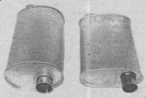
Shown here is the original muffler for a turbocharged CORVAIR model (left). It was designed for a 6-cylinder turbocharged engine. Since turbochargers themselves significantly reduce noise levels, such a silencer provided only a minimal reduction in noise. When installed on a conventional engine, this muffler was very noisy. There are many mufflers called "turbos" (such as the one shown on the right), but only a few provide good noise reduction and low flow resistance.
Luckily, it's fairly easy to distinguish between good and bad ceramic blocks without using a test rig. A reliable estimate can be made by shining a light inside the muffler and checking the center pipe. If the channel decreases significantly in size from inlet to outlet, or if you cannot see the outlet at all, then it is better not to buy such a muffler. Second, check the holes punched in the center tube that allow exhaust gases to enter the material ceramic block. If they protrude into the flow of gases like small caps, then this will significantly increase the restriction of the flow and interfere with it.
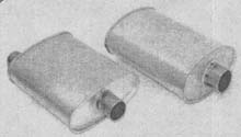
Some "turbo mufflers" bear little resemblance to actual uprated designs. In fact, some of them have more flow resistance than standard mufflers; others are almost as noisy as plain pipes.
However, if the holes are punched outward from the center tube and directed towards the outer casing, then this is a quality muffler. Now we can conclude: a ceramic block with holes in the center tube punched outward almost certainly produces more noise. You can use 2 or 3 of these ceramic blocks in each exhaust pipe to achieve an acceptable noise level.
Reverse flow Forward flow
Correct and incorrect installation of a ceramic block with holes punched inward. 1 - reverse flow; 2 - direct flow.
Exhaust gases normally passing through an inwardly punched center pipe will hit the top edge of each hole and travel backwards along such a tooth, greatly increasing drag. However, if the muffler is installed in reverse, the exhaust gas flow will break near each tooth. The difference between forward and reverse flow can be very large and reaches almost 50%. However, installing a ceramic block with holes punched inwards also increases the noise level. In fact, since the "reverse", i.e. internal, holes tend to close the inlet channels to the material of the block, the noise level can be even higher than that of a muffler with holes in the central pipe punched outward.
Always check the holes punched in the center tube. If the holes are punched outward from the center pipe and towards the outer casing, and the center pipe is large (as shown below), then such a muffler can be considered a good muffler.
Building the exhaust system
The exhaust system consists of a system of connecting pipes that direct exhaust gases from the exhaust manifolds to the rear of the vehicle.System design and pipe size
First of all, every uprated V8 engine must be equipped with a dual exhaust system. The average V8 engine produces a significant amount of hot exhaust gases at high engine speeds. If all these gases are directed through the same exhaust pipe and muffler, then such a system almost always suffers from excessive back pressure. To avoid this, there are two ways to go. First: to install a practical double exhaust system with silencers that provide high gas flow rates. Second, find space for a pipe with an orifice of 89 to 100 mm and a single muffler that allows a flow of 17 to 23.7 m3/min, such as a muffler from a truck with a diameter of 300 mm and a length of up to 1200 mm.Assuming you've opted for the more practical dual exhaust system, the question now is what should be the diameter of the pipe that connects the exhaust manifolds to the mufflers. Most engine boosters fit 63.5mm pipe as that is the usual size for standard mufflers, and larger pipes often require additional bending and can create underbody clearance problems. From a practical standpoint, a 63.5 mm pipe is suitable for most everyday use engines up to 400 hp. with. and even more. If the engine is producing significantly more power or has exhaust manifolds that have 100mm downpipes, you may need larger pipes. However, clearance constraints may require a "stepped" solution. For example, a 100 mm pipe extends a short distance from the exhaust pipes, and then gradually narrows to a size of 63.5 mm at the mufflers. However, before you decide to use pipes larger than 63.5 mm, always keep in mind that the relatively straight pipe from the downpipe flange to the muffler has less flow resistance than mufflers. Use only the best high flow mufflers (often with pipe diameters greater than 57.2 and 63.5 mm) and, if possible, use pipes that are no smaller in diameter than the muffler inlet.
Let's take a look at a situation that can occur in the case of an engine for everyday use, where ground clearance is an important factor. The 57.2mm pipe is the largest size that can be used to connect the manifold and muffler. However, a muffler with a 57.2 mm inlet and an inner pipe of the same size will almost certainly allow less flow than a muffler with a 63.5 mm pipe. To optimize this system, use a larger muffler with a 63.5mm inner tube (since even the largest muffler remains the most restrictive element of the system) and add a short adapter in front of the muffler to increase the pipes from 57.2mm to 63.5mm. Never downsize the exhaust manifold downpipe when changing to a muffler with a smaller center pipe.
Bends in the exhaust system
It is practically impossible to use only straight pipes in the exhaust system. It is necessary to bend the pipes to bypass the transmission and suspension parts. Unfortunately, each bend increases back pressure and reduces engine power. The flow resistance will be reduced if larger pipes are used in areas with bends. Always use bends as large as possible. Avoid sharp bends or bends in pipes, as any internal unevenness in the pipes will increase back pressure.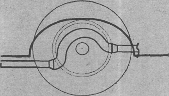
Plan your exhaust system carefully.
Cross pipes
A large number of Bench and sea trials have shown that a simple cross pipe connecting the two sides in a dual exhaust system just behind the exhaust pipes and in front of the mufflers can increase engine power. The increase in power from the use of a transverse tube occurs in both conventional and racing cars, but the reasons for the increase in different cases.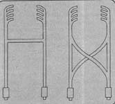
Exhaust systems with transverse pipes can be created in various ways. A single straight cross pipe is allowed when the flow capacity of the muffler is high enough. A double cross pipe system will increase power if the mufflers have more flow resistance or if it is used on engines over 350 hp. with. The more resistance the mufflers have, the more power can be obtained from using a cross pipe system.
On a racing car with an open exhaust system and a cross pipe between the exhaust pipes, this pipe transmits the shock waves of the exhaust gases from one side of the system to the other. On conventional vehicles, the cross tube performs additional function: The cross pipe allows each side of the engine to partially share the combined muffler's flow capacity. Although even the most efficient cross pipe will not double the flow in the system, 25% improvement is common.
Numerous bench and driving tests have shown that a simple cross pipe connecting the two sides of a dual exhaust system just after the exhaust pipes and in front of the mufflers can increase engine power.
twin mufflers
Sometimes it is not possible to reduce exhaust back pressure to an acceptable level with a single muffler on each side of the exhaust system. This often happens on high powered, large displacement engines (i.e. over 6500cc). If the measured pressure in the system is more than 0.35 kgf/cm2, then it may be necessary to use two silencers on each side, which are connected in parallel.
Staggered arrangement of mufflers.
In these cases, the exhaust gases from each block of cylinders pass through two mufflers (see figure below) and only 4 mufflers are required for a V8 engine. If the Y-junction that distributes the exhaust between each pair of mufflers is properly designed, the effective flow of the two mufflers will be approximately double that of a single muffler on either side.
The most obvious disadvantage of twin mufflers, other than the price, is that there is not enough clearance under the body on most vehicles to accommodate two mufflers next to each other. Some designers use a staggered arrangement of twin mufflers, which requires less space, but in all cases it is important to remember that bends and transitions from one pipe to two and back again should be smooth, of a larger diameter and, if possible, of a known manufacturer.
Practical examples
The obvious question here might be: what gains in power and economy can be expected if the entire exhaust system is completely redesigned with an emphasis on reducing back pressure? The increase can be different, but the following examples will show what is possible to obtain.The first engine is an experimental four-cylinder test-bench engine originally fitted with an industrial design muffler (a typical backflow design used on many vehicles) and a large diameter, short, straight exhaust pipe. After measuring the main power curve, the standard muffler was replaced with a special design that provided almost zero flow resistance. In fact, tests carried out on the bench showed a fairly noticeable increase in power compared to the previous exhaust system. With no other changes to the engine, the reduced back pressure resulted in an 8% power gain across the entire rev range. Fuel economy improvements of 3-8% have been seen with a typical value of around 6%.
The practical use of the discussed changes could also be seen on one of the test 5735cc V8 engines originally equipped with a commercial single exhaust system. To determine the baseline, the standard power was measured, which amounted to 152 hp. with. with an exhaust system that has an abnormally high back pressure of 1.13 kgf/cm2. The standard ball catalytic converter was then removed and the industrial muffler was replaced with a CYCLONE SONIC TURBO muffler. Power at the same time jumped to 210 liters. s., and the back pressure in the exhaust system decreased to 0.25 kgf/cm 2 . Finally, a dual exhaust system was installed, which was carefully crafted to reduce back pressure. Equipped with CYCLONE SONIC twin turbo mufflers but still using stock exhaust manifolds, this unit delivered a noticeable power boost of up to 47% over the standard exhaust system. The measured power was 224 liters. s., and the back pressure in the system was less than 0.07 kgf/cm 2 . However, such an increase in power is not only due to large material costs when purchasing parts. A high flow dual exhaust system can be noticeably noisier than a standard or even modified single exhaust system. In fact, some systems with turbo mufflers may not meet noise requirements.
If a vehicle is to meet emissions requirements, a catalyst must be part of the exhaust system. Fortunately, power losses can be reduced if dual honeycomb catalysts are used. They should be located in front of the mufflers and as close as possible to the exhaust manifolds. The resistance can be further reduced by changing the inlet and outlet of the catalyst into long conical channels. As additional benefit Catalysts also reduce noise from the exhaust system.
exhaust manifolds
At first glance, the task of removing exhaust gases from the cylinders may seem simple, not requiring any special design tricks. However, as mentioned earlier, the internal combustion engine is a complex machine that operates with a carefully thought-out interaction of many dynamic systems. However, exhaust manifolds allow the engine to "breathe" more easily by reducing the pumping losses that occur when the piston moves up on the exhaust stroke. This is the most obvious advantage tubular intake manifolds have to offer.If the exhaust stroke occurs only once, then making exhaust manifolds would be a simple task to reduce flow resistance. But even at 2000 rpm, the V8 engine delivers about 70 exhaust strokes per second per bank of four cylinders. These pressure pulses, as we shall see, interact with the exhaust gas flow to form a complex dynamic mixture that can affect optimal size collector pipes, their length and overall design. It can be quite difficult to fully understand flow dynamics, but exhaust system tuning can be the "key" to getting extra power. You will need the right combination and here are some guidelines for getting the best results.
Tubular or solid manifolds?
Exhaust manifolds can improve engine power, but they are not always the best choice for a conventional uprated (non-racing) engine. While tubular manifolds are more efficient in the medium to particularly high rpm ranges, if the engine is running at low rpm, then cast iron manifolds give good performance, are cheaper (if you already have them), more compact and less prone to forming. exhaust leaks. Cast manifolds are ideal for utility vehicles where low rpm torque is critical. If you have a highly boosted engine, you can get a noticeable boost in power and fuel efficiency by using the exhaust manifolds that are found on regular powerful engines.
The FORD INDY DOHC engine shown here uses one of the well-known tubular exhaust manifold designs.
One-piece exhaust manifolds are inefficient at high flow rates and high RPMs due to their design. Almost all manifolds, including even uprated designs, have short passages that combine into a common chamber having a design that doesn't "care" about flow. When exhaust gases enter the exhaust manifold, they encounter two main obstacles:
channels with flow resistance;
the impulses from each cylinder influence each other and greatly increase the resistance to flow, since the lengths of the individual pipes for the different orifices are often very small.
How exhaust manifolds work
Tubular exhaust manifolds suffer from both of the above disadvantages. By increasing the length of each pipe and smooth bends, as well as effectively isolating individual channels, the use of a tubular-type exhaust manifold improves flow and virtually eliminates the effect of cylinders on each other. When exhaust manifolds are combined with an efficient exhaust system (high flow mufflers, etc.), additional power can be obtained by blowing out the cylinders.Inertial and wave blowing
It would seem that a device made of metal pipes and with no moving parts could draw in a fresh air-fuel mixture through an open intake valve almost over a stagnant piston and help rid the combustion chamber of exhaust gases. It's like installing a turbocharger that needs no power input: no drive belts, no spinning turbines; it delivers the extra power it needs. It may seem surprising, but tubular exhaust manifolds can provide this power boost when they are properly made. So let's take a look inside the pipes and see how this imaginary "turbocharger" works.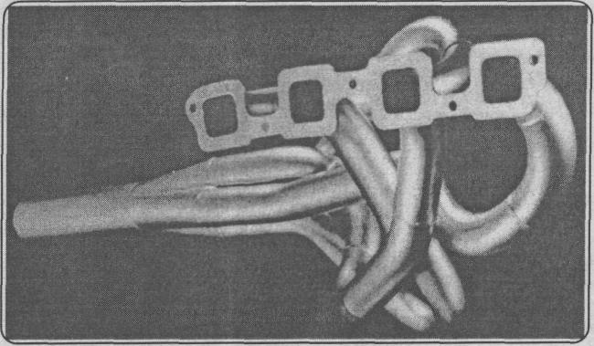
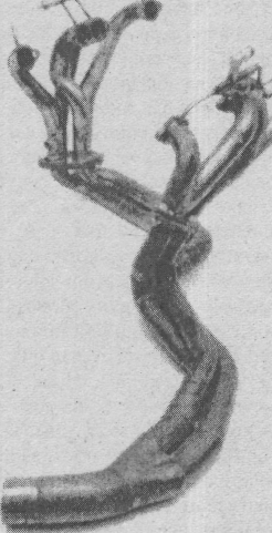
This large-diameter tangle of pipes is STAHL's STREET HEMI exhaust manifold, which uses inertial scavenging and resonant tuning to clean exhaust gases from combustion chambers and improve power.
As pressure pulses pass through each exhaust pipe, they can carry energy, which acts in two ways to generate a scavenging effect and improve power. First, the moving mass of gases has inertial properties. Inertia is the tendency of moving bodies to resist any change in their motion. The flow of high-pressure gases that exit the cylinder head passages tends to keep moving through the manifold pipes, and the inertia of these gases, if strong enough, will draw additional air-fuel mixture through the open intake and exhaust valves when the valves overlap.
There is also a second way in which exhaust manifolds help expel exhaust gases from a cylinder: shock wave low pressure, formed when the high pressure exhaust gas pulse exits the system, can help draw additional air-fuel mixture into the cylinder when the valves overlap. To make it easier to understand how this mechanism works, let's choose one collector pipe. As already mentioned, when the intake valve opens, exiting under high pressure gases "jump out" into the pipe and a pressure pulse is formed. This pulse, traveling at the speed of sound, quickly reaches the end of the exhaust pipe, where a sub-atmospheric reflected wave forms. This backward wave travels back through the pipe to the outlet valve also at the speed of sound, which varies with temperature, but is typically 360-400 m/s. By changing the length of the primary manifold pipe, the time required for the pulse to return to the outlet will vary. By careful selection of this length, it is possible to adjust the return time of the low pressure wave to the engine speed. For a specific length of pipe and a specific engine RPM, the low pressure pulse can be fine-tuned to reach the exhaust port when the valves are closed, where it will help purge residual exhaust gases that the piston cannot force out of the combustion chamber. This reflected wave, in turn, causes air-fuel mixture flow to be drawn into the cylinder through the open intake valve before the piston begins its intake stroke.
Adjusting the length of the tubular exhaust manifold to optimize reverse wave scavenging is called resonant tuning. Unfortunately, there are always disadvantages in engine building, which accompany obtaining an increase in power. The length of the exhaust manifold pipe provides right time to return the reverse pulse only in a narrow range of engine speeds. If this pipe is relatively short, then the resonant effect occurs in the high speed region; if it is relatively long, then the effect appears in the region of low engine speeds.
Exhaust manifold setting
like others important details for power, whether inside or outside the engine, the exhaust manifold is one part of the engine's "breathing" system. To be most effective, it must work in conjunction with other parts of this system. The "command center", which determines the characteristics of the exhaust "breathing" system of the engine, is the camshaft, and General characteristics exhaust system can be directly linked to the camshaft timing. The choice of the camshaft essentially determines in what region of engine speed will be achieved - maximum power and torque. For a racing engine, the lengths and diameters of the exhaust manifold parts must be combined with the characteristics determined by the camshaft. For high RPM, the exhaust manifold design must include large diameter pipes and relatively short and large diameter downpipes. For everyday engine performance and fuel efficiency, the exhaust manifolds are designed with small diameter pipes and relatively long lengths.It is always dangerous to make any generalizations, but due to the commonality in the designs of most V8 engines, two statements can be made. The first is that, with the exception of cars with exhaust gas blowing, exhaust manifolds without exhaust pipes practically do not work. The single-pipe design is effective on racing-fueled vehicles, as the turbocharger completely bleeds through the cylinders, directing the header pipes to other parts. Secondly, almost all "regular" exhaust manifolds consist of four separate pipes connected to form a large exhaust pipe. This design makes it possible to use the interacting shock waves generated in the V8 engine from cylinder to cylinder, and is the best choice for high performance and racing engines.
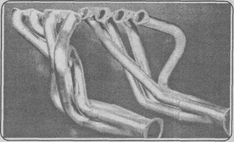
Exhaust manifold the best design consists of 4 separate pipes connected to a large diameter downpipe.
Finding the optimum pipe diameter and length for a racing engine always requires a lot of bench testing. Trial and error is one reliable way to find parts that will perform well in a given RPM range. This uncertainty is mainly due to the fact that each exhaust manifold produces a lot of shock waves that make accurate analysis difficult. Fortunately, a re-examination of the basic design of V8 engines will simplify our understanding of how the exhaust manifold works and can provide some basic guidelines for overall manifold design and pipe selection.
Such special "exhaust manifolds 180° design" were installed on the lines special purpose, and the STAHL bolt-on design was produced for sports models.
Many people tend to think of a V8 engine as two inline 4-cylinder engines on a common crankshaft. In fact, this is far from the case. A V8 engine is essentially 4 V2 engines connected together in a 90 degree sequence. This design produces an uneven exhaust stroke divided into each block of cylinders. This somewhat reduces the power potential of the exhaust manifolds divided into cylinder blocks (4 cylinders per manifold).
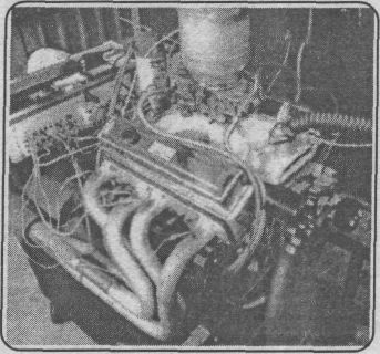
Determining the best pipe diameter and length for a racing engine always requires a lot of bench testing. The uneven separation of the exhaust stroke on V8 engines results in this mixing of shock waves in each of the cylinder blocks. Trial and error is often the only sure way to optimize a design and get the most power.
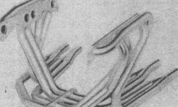
To ensure an even cylinder purge sequence on a V8 engine, some of the manifold pipes must intersect with the opposite cylinder block. Such systems are commonly known as the 180-degree design, as an exhaust gas pulse occurs in each exhaust pipe every 180° of crankshaft rotation. The disadvantages of this system are the rather critical exhaust manifold pipe lengths and that typical V8 engines require pipes so short that they are often impossible to make due to inappropriate cylinder head spacing.
Exhaust manifolds divided by cylinder blocks
While the split-by-cylinder system (4 cylinders to 1 manifold) is slightly less efficient than the 180-degree exhaust manifold, the upside is that it is less sensitive to pipe length. In fact, a large amount of bench testing is required just to determine the optimal length of pipes while getting a few extra horsepower when building a racing engine.
While a split exhaust system is slightly less efficient than a 180-degree exhaust manifold, it is much less sensitive to pipe length and is much easier to make and install on a vehicle.
Bench tests have shown that most engines are insensitive to the shape of the channels through which the exhaust gases exit the head of the block (exhaust channels). Moreover, while the overall design of the exhaust manifold provides flow, there is no great sensitivity to unevenness in the pipes (sometimes closed up to 2/3 of the outlet in one cylinder), to changes in the length of the pipes and their diameter, but there is a great sensitivity to the number of bends and to their radii. Strong bends greatly increase the resistance to flow and smooth out the effect of scavenging, and this almost always leads to a decrease in power.

DOUG THORLEY's three-Y tubular exhaust manifold has a simplified overall design, fewer bends and low cost.
Luckily, tube lengths ranging from 550mm to 1200mm produce very close power on most uprated or racing engines. This length insensitivity is very useful, as it simplifies under-vehicle installation and allows for an optimal overall design. Don't worry about the almost imperceptible effect of unequal exhaust manifold lengths - a change in length of up to 300mm or more shows very little power variation. It is possible to optimize power by reducing flow resistance by reducing the number of bends and increasing their radii.
Three Y exhaust manifolds
Intensity along length is the main reason triple Y exhaust manifolds perform well. The "three Y" design combines 4 primary pipes into two pairs of secondary pipes approximately 1/3 of the distance to the downpipe. This "4->2->1" configuration greatly simplifies the overall design, reduces the number of bends, and reduces the cost. The tests that were done on these manifolds showed that they produced only slightly less power than a quality "4->1" exhaust manifold. This was especially evident when working with camshafts that provide a valve opening time of more than 270 °. However, when even the best 3-Y manifolds are used with camshafts that provide more than 270° valve openings, they often provide significantly less maximum power than quality 4->1 exhaust manifolds.For use in everyday engines, "three-Y" manifolds should be seriously considered as a practical step between solid exhaust manifolds and "4->1" manifolds. Although many enthusiastic designers consider "three Y" manifolds to be more suitable for low compression engines used in trucks. Quality triple-Y manifolds provide good power levels in medium displacement engines for everyday use, especially when used in conjunction with high-flow exhaust systems that include a cross-pipe running between the manifolds. In addition, triple Y manifolds often produce a wider range of power than many 4->1 systems, which is an additional reason for their use in everyday heavy vehicle engines or in conjunction with automatic transmissions.
Exhaust manifolds A.R.
IF you are making a boosted engine for installation in a car with an automatic transmission, then efforts should be directed to optimizing torque at low revs. To achieve this, some enthusiastic designers may choose an exhaust manifold with relatively small diameter (38-41 mm) primary pipes, since small pipes maintain high exhaust velocity, improve inertial scavenging and provide good values torque at low and medium speeds. Unfortunately, these small diameter pipes create additional flow resistance at high engine speeds, especially on 325 hp engines. with. and more. On the other hand, if you use large bore primary tubes to improve high rpm power, low rpm scavenging efficiency will decrease and torque and fuel efficiency will suffer at typical driving rpm. It may seem that you can adjust the power from one or the other end of the rev range; it is impossible to have it at both ends of the range. This was in most cases before the introduction of A.R. exhaust manifolds.Title "A.R." in the designation of the collectors corresponds to the name "ANTI-REVERSION" and is a trademark of CYCLONE and BLACK JACK. "REVERSION" refers to unwanted reverse flow of exhaust gases into the intake system, which can occur when the exhaust gas velocity in the primary manifold pipes is low and the inertial scavenging has insufficient energy to draw the air-fuel mixture into the cylinder when the valves overlap. In this situation, the back pressure in the system pushes the exhaust gases into the intake system passages. This phenomenon usually occurs at low rpm, especially when large bore exhaust manifolds are combined with high valve timing camshafts.
The A.R. exhaust manifold design uses large diameter pipes to achieve high power at high rpm. However, the manifold is internally designed to reduce backflow, resulting in a scavenging effect and reduced backflow on most small bore exhaust manifolds. The following table shows the basic operation of the A.R. Manifold: A direction-sensing and anti-backflow cone is mounted on the surface of the manifold, providing little resistance to forward flow but markedly restricting reverse flow. In addition, A.R. manifolds allow useful waves negative pressure flows easily to the valves and combustion chamber and limits positive pressure waves that reduce engine power. Although A.R. exhaust manifolds are less sensitive to pipe diameter, pipe size still determines to some extent how much maximum power will be delivered over the engine's rev range. Before choosing a particular manifold, discuss its intended use with the manifold manufacturer and take into account the recommendations given to you. However, the disadvantages of using an A.R. manifold primary tube diameter that is too large for the application is smaller than a conventional manifold.
The SLP ENGINEERING exhaust manifolds shown here are designed for uprated engines of CHEVROLET CAMARO and PONTIAC FIREBIRD vehicles.
The A.R. exhaust manifold can also, in many cases, effectively compensate for some of the power loss associated with reverse flow resulting from exhaust system mismatching. For example, low RPM backflow is commonly caused by camshaft profiles with too long valve timing and/or valve overlap, an intake manifold designed for high RPM operation, or a carburetor with too much flow capacity for the engine. A.R. exhaust manifolds offset the power losses associated with these parts.
Finally, A.R. manifolds can also contribute to the amount of part-throttle torque and engine fuel efficiency. For survival races where fuel consumption is a big factor, using A.R. manifolds can increase your chances of winning. In fact, A.R. manifolds seem to make positive contributions in all areas, from quick throttle response on a conventional car to fast cornering on a race track. Virtually without exception, comparative tests of conventional exhaust manifolds and A.R. manifolds have shown that the A.R. design is the best. This can in many cases provide better low and high rpm power combined with improved fuel efficiency. This is the rare case when you can have everything!
There are two other important aspects of the use of A.R. exhaust manifolds that have come to light in both bench and drive tests. The first is that you must use a cross pipe with an A.R. header to contribute to the reduction of backflow. Without a cross pipe connecting both downpipes (or exhaust pipes next to the downpipes), most of the low end torque and fuel efficiency benefits will be lost and the A.R. manifold will operate like a regular exhaust manifold. It is not known exactly why this happens, but it happens in almost all cases. Always use cross pipe with A.R exhaust manifolds.
Second, the A.R. manifolds "clean" the carburettor by improving the vacuum at the additional diffusers. In fact, the higher vacuum of the additional diffusers from the A.R. manifolds allows the use of smaller jets to achieve the same air/fuel ratio. If you are using a single quad HOLLEY carburetor, the primary and secondary fuel jets will need to be reduced 1-2 sizes, and in some cases 3-4 sizes, to achieve the correct air/fuel ratio.
Exhaust Manifold Operation A.R.

A.R. exhaust manifolds use a cone that senses direction of flow and prevents backflow of exhaust gases. It is installed on the surface of the collector inside large diameter primary pipes. This provides low resistance to forward flow and increased resistance to unwanted reverse flow. 1 - high direct flow of exhaust gases; 2 - low return flow of exhaust gases when the valves overlap.
A cross pipe must be used with exhaust manifolds. Without this pipe connecting both downpipes, most of the low end torque and fuel efficiency benefits would be lost.

Exhaust Manifold Tuning/Additional Parts
Benefits of A.R. Manifolds and Standard Exhaust Manifolds
A.R. exhaust manifolds benefit from a backflow-preventing cone welded at the junction of the primary pipes and the mounting flange. These cones are sensitive to the direction of flow and help

Shown here are power and torque curves for a boosted 5359cc engine fitted with AIR FLOW RESEARCH cylinder heads. The engine would not run at wide open throttle below 2800 rpm with standard "4->1" exhaust manifolds. After installing the exhaust manifolds and optimizing the single 4-barrel carburetor, the engine produced consistent power at wide open throttle throughout the entire rev range from 1800 rpm. 1- engine power with collectors A, R.; 2- engine power with conventional exhaust manifolds; 3- engine torque with CYCLONE A.R. exhaust manifolds; 4 - engine torque with conventional exhaust manifolds.
reduce the flow of exhaust gases entering the air-fuel mixture. A similar, though less efficient, directional flow can be obtained in a conventional exhaust manifold by introducing a mismatch between the exhaust manifold flange orifice and the exhaust port. To obtain flow restriction in the desired direction, the hole in the exhaust manifold flange must be larger than the diameter of the exhaust port. The mismatch between the channel and the flange will have very little effect on the flow from the channel, since the exhaust gases enter the large diameter pipe with less resistance, and the protruding edge due to the mismatch in size will significantly reduce the return flow into the channel. The result will be that some of the low to mid range power and torque gains provided by A.R. manifolds may appear on performance curves for an engine with conventional manifolds.

A small effect, similar to that of using A.K. type exhaust manifolds, can be achieved in conventional exhaust manifolds by introducing a properly spaced mismatch between the holes in the intake manifold flange and the exhaust port in the cylinder head.
The sizing mismatch between manifold and duct must be carefully sized, otherwise overall exhaust duct flow and power may suffer. Never create a mismatch between the size of the exhaust manifold flange and the bore in the cylinder heads at the top of the bore. All "useful" discrepancies should be located at the bottom of the channel, where the flow rate is minimal. To correctly place the mismatch, it is important to consider the location of the exhaust manifolds on the surface of the cylinder head. It may be necessary to weld and re-drill the mounting holes in the manifold flange, or install adapter plates on the heads and drill new holes in the flanges.
One note: if you are using adapter plates, treat the channels in the plates as extensions of the outlet channels. To optimize channel flow, adapter plates must be connected to the heads before the cylinder heads are inspected and tested.
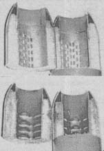
Keep Warm
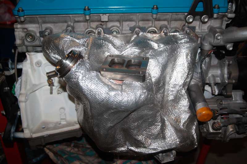
Exhaust manifolds help clear exhaust gases from the cylinders and help the intake system draw in the air-fuel mixture. The energy for this is taken from the energy contained in the exhaust gas stream itself. The more energy that can be held inside the pipes until the gases escape into the downpipe and into the exhaust system, the more efficient the exhaust manifold will work. One of these forms of energy is heat, and heat is related to the volume of exhaust gases and their velocity in the collector pipes. When heat is dissipated from parts of the exhaust system, the velocity of the exhaust gases is reduced and in some cases this can reduce the scavenging effect.Heat dissipation from the exhaust manifolds can affect other horsepower, perhaps even more. in an efficient way: it is dissipated in the engine compartment, where it heats the exhaust system and intake air. Bench tests show that an increase in the temperature of the incoming air by about 6 ° C reduces engine power by 1%.

Thermal insulation parts from THERMO-TEC keep more energy inside the exhaust manifold pipes until the exhaust gases exit into the downpipe or exhaust system, which increases the efficiency of the exhaust manifold and turbocharger.
For these and other reasons, including safety, thermal insulation of exhaust system parts has become quite popular. The materials for this resemble fabric and have a different configuration: stripes, sheets and circles. Most insulation kits include zip ties, high temperature braiding. These parts are pretty easy to install.
Additional parts for exhaust manifolds
Some exhaust manifold manufacturers, including STAHL HEADERS, offer exhaust manifolds in kit form as well as fully assembled ones. Kits include bent pipe pieces, flanges and downpipes that must be assembled into a single unit. Or they may be bent primary header pipes that are lightly pre-welded to the flanges and only need to be finally welded to the flanges and downpipes. In any case, exhaust manifolds sold in kit form are noticeably cheaper and allow the designer to add some parts for special purposes or experimental tuning.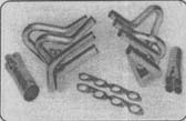
The STAHL HESDERS set shown here is much cheaper than already assembled knot and it is very handy if you want to make some modifications.
Most manufacturers also offer a wide range of individual bent pipes, downpipes, flanges, bolts, A.R. cones, gaskets and other parts needed to make exhaust manifolds. STAHL HESDERS sells a variety of mis-bent pipes, which are pieces of pipes that have been bent incorrectly during the production of tubular exhaust manifolds. These are new pipes of various shapes, the length of which can reach up to 13 m, and the diameter can be selected from 32 mm to 54 mm in 3 mm increments. Such details make it possible high costs to make an exhaust manifold for any exhaust system.
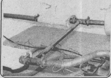
Vacuum removal systems
Over the past 10 years, the benefits of applying vacuum to the oil pan have become well known. The low pressure inside the engine helps prevent detonation by reducing contamination of the incoming air-fuel mixture and combustion chamber with oil from the engine's lubrication system. In addition, it also helps prevent oil leaks from gaskets and seals and can often result in extra power by limiting losses due to oil drag.Such advantages can be very important on racing engines, but they are of less practical importance for everyday uprated engines. On "everyday" engines, the compression ratio is noticeably lower and low-force oil scraper rings are rarely used, which significantly reduce the potential knock caused by oil entering the combustion chamber. However, for those who wish to consider adding a vacuum system to their uprated or racing engine, the following information is addressed.
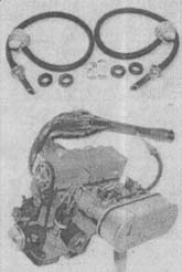
The kit from EDEL BROCK contains parts to create a "racing" system on conventional engines. The nozzle is welded into the exhaust system and a low pressure (vacuum) is created in it when fast moving exhaust gases pass by the nozzle.
At high speeds, the exhaust gases move through the exhaust manifolds at a speed sufficient to be used as a kind of air pump. A kind of nozzle is welded into the system, usually in the area of \u200b\u200bthe downpipe, where low pressure is formed from the exhaust gases passing by. This low pressure (vacuum) can be used with one of the commercially available vacuum removal systems. The receiving nozzle is connected to a one-way valve (backfire prevention valve) that receives low pressure pulses, which are then fed to the engine through an oil separation chamber. This chamber returns the collected engine oil back to the oil pan. This vacuum system, powered by the exhaust manifold and coupled to the intake manifold vacuum system to maintain low pressure at part throttle, will maintain a vacuum inside the engine at all power levels.
Not surprisingly, an exhaust manifold "driven" vacuum system works best with open exhaust manifolds (i.e. no exhaust pipes, mufflers, etc.). However, if the engine power is less than 400 hp. with. If you are running a high-flow exhaust system with dual tailpipes, the vacuum removal system can also work with a complete exhaust system. But even if it is possible to operate a vacuum system with a source in the exhaust manifold on a conventional engine, there are disadvantages that must be considered, especially when the intake manifold vacuum system is also used to maintain vacuum in the oil pan at idle and part-throttle. If the engine has a sufficiently high vacuum, then oil may not flow to the valve guides, and accelerated wear of the valve train parts will take place. This can happen even when using bronze valve guides that are installed without valve stem seals (stem seals). However, bronze guide bushings from A.R.T. or K-LINE work well in low oil conditions and are the best choice for conventional and racing engines that use a vacuum system.
In conclusion, in addition to increased reliability due to knock prevention and slight power gains from reduced drag, a vacuum bleed system may be a necessary addition to truck and racing engines. Why? Because it prevents oil leaks, which is a serious concern for riders. A few drops under the car before the start of the race can mean disqualification of the driver and the car, and can even lead to disaster. In the pursuit of making a racing engine and keeping it in good condition, a vacuum supply system can prevent oil leaks from misplaced gaskets, worn seals, and loose bolts. In fact, one of the test engines for racing truck with a 3mm hole on the side of the oil pan (the hole was punched during the race) had no oil leakage when it was running and there was a vacuum in the oil pan. This allowed the rider to finish the race (and not so easy, but to win), but when the rider turned off the engine, almost all the oil from the engine pan spilled onto the ground.