Used exemplary instruments and additional equipment.
Touch sensor for Arduino
The module is a touch button; a digital signal is generated at its output, the voltage of which corresponds to the levels of logical ones and zero. Refers to capacitive touch sensors. We encounter such input devices when working with the display of a tablet, iPhone or a touchscreen monitor. If on the monitor we press the icon with a stylus or a finger, then for this we use an area of the board surface the size of a Windows icon, which is touched only by a finger, the stylus is excluded. The basis of the module is the TTP223-BA6 chip. There is a power indicator.
Melody playback rhythm control
When installed in the device, the touch area of the module board surface is covered thin layer fiberglass, plastic, glass or wood. The advantages of a capacitive touch button include a long service life and the possibility of sealing the front panel of the device, anti-vandal properties. This allows the touch sensor to be used in outdoor appliances in direct contact with water droplets. For example, a doorbell button or Appliances. Interesting application in equipment smart House- replacement of light switches.
Characteristics
Supply voltage 2.5 - 5.5 V
Touch response time in various current consumption modes
low 220 ms
typical 60 ms
Output signal
Voltage
high log. level 0.8 X supply voltage
low log. level 0.3 X supply voltage
Current at 3 V supply and logic levels, mA
low 8
high -4
Board dimensions 28 x 24 x 8 mm
Contacts and signal
No touch - the output signal has a low logic level, touch - a logical unit at the sensor output.
Why it works or some theory
The human body, like everything that surrounds us, has electrical characteristics. When the touch sensor is triggered, our capacitance, resistance, inductance appear. On the underside of the module board there is a section of foil connected to the input of the microcircuit. Between the operator's finger and the foil on the bottom side there is a dielectric layer - the material of the carrier base of the module printed circuit board. At the moment of contact, the human body is charged with a microscopic current flowing through a capacitor formed by a piece of foil and a human finger. In a simplified view, the current flows through two capacitors connected in series: a foil, a finger located on opposite surfaces of the board, and the human body. Therefore, if the surface of the board is covered with a thin layer of insulator, this will lead to an increase in the thickness of the dielectric layer of the foil-finger capacitor and will not disrupt the operation of the module.
The TTP223-BA6 microcircuit captures a tiny microcurrent pulse and registers a touch. Due to the properties of the microcircuit, this technology does not cause any harm to work with such currents. When we touch the case of a working TV or monitor, microcurrents of greater magnitude pass through us.
Low Power Mode
After power is applied, the touch sensor is in a low power mode. After triggering for 12 seconds, the module goes into normal mode. If further contact does not occur, the module will return to the reduced current consumption mode. The response speed of the module to touch in various modes is given in the specifications above.
Work with Arduino UNO
Download the following program to the Arduino UNO.
#define ctsPin 2 // Contact for connecting the touch sensor signal line
int ledPin = 13; // Pin for LED
Void setup() (
Serial.begin(9600);
pinMode(ledPin, OUTPUT);
pinMode(ctsPin, INPUT);
}
void loop() (
int ctsValue = digitalRead(ctsPin);
if (ctsValue == HIGH)(
digitalWrite(ledPin, HIGH);
Serial.println("TOUCHED");
}
else(
digitalWrite(ledPin,LOW);
Serial.println("not touched");
}
delay(500);
}
Connect the touch sensor and Arduino UNO as shown. The circuit can be supplemented with an LED that turns on when the sensor is touched, connected through a 430 Ohm resistor to pin 13. Touch buttons are often equipped with a touch indicator. This makes it easier for the operator to work. When a mechanical button is pressed, we feel a click regardless of the reaction of the system. Here, the novelty of the technology is a little surprising due to our motor skills that have developed over the years. The pressure indicator saves us from an excessive feeling of novelty.

The circuit proposed for repetition is an amplifier with high sensitivity to the electromagnetic field created by external devices. When the input contact of the circuit is connected to the antenna, the LED signals the presence of electromagnetic field radiation and interference from electrical equipment. The LED will also indicate the fact of touching the contact, since the role of the antenna in this case is performed by the human body. Hence the name - touch sensor. Another name for the circuit is an active antenna.
circuit diagram touch sensor is shown in Figure 1.
The circuit resembles an oscillator on transistor n-p-n structures. One of the terminals of the winding L1 is connected directly to the input contact X1. The polarity of the VD1 LED does not matter. Resistor R2 limits the current through the LED and, thereby, determines the brightness of its glow when the sensor is triggered.
The touch sensor is assembled on breadboard size 40 × 40 mm. Appearance structure is shown in Figure 2.
 |
|
| Figure 2. | Appearance of the touch sensor. |
Windings L1 and L2 are located on a common frame with two sections for winding and a tuning ferrite core. Outside diameter frame - 10 mm, core length - 23 mm, thread diameter at the base of the core - 6 mm. In the design shown in Figure 2, L1 is wound on the top section, L2 on the bottom. Each coil contains 100 turns of PEL 0.2 wire. Windings included according to. Using a screwdriver, the core is screwed into the frame. VD1 LED - any of the AL307 series. As X1, a ground lobe is used. Touching it causes the LED to light up.
VD1 can be connected in parallel measuring device, for example, a multimeter in voltage measurement mode, which will allow you to evaluate the level of field strength. In this case, the external antenna may be a piece of mounting wire several centimeters long. Setting up the circuit will come down to choosing the length of the antenna and finding such a position of the core at which the voltage on the LED is maximum.
The scheme is not picky about the choice of element base. For example, in the original version of the circuit, the KT815G transistor was used, the resistance of the resistor R1 was 100 kOhm. As L1 and L2, two coils on a rod ferrite core of a long-wave magnetic antenna from a radio receiver were used. Coils could be moved along the core. When moving the coils, phenomena were observed that did not contradict the law of electromagnetic induction, in contrast to the scheme proposed in. With a significant distance of the coils from each other and without a ferrite core, the circuit stopped working.
The circuit can find practical application not only in the design of field strength meters, but also in automation and signaling devices. The touch sensor can be connected to the microcontroller. To do this, perform an analog-to-digital voltage conversion on the VD1 LED, possibly using the resources of the microcontroller itself, if it contains a built-in ADC.
In conclusion, it should be noted that there are many touch sensor circuits based on field-effect transistors and not containing inductive elements. Perhaps their work is more efficient in many cases, but the design given in this article is an example of the original technical solution and is aimed at beginner radio amateurs.
Literature
- Brovin V. I. The phenomenon of energy transfer of inductances through the magnetic moments of a substance located in the surrounding space, and its application. - M.: MetaSintez, 2003 - 20 p.
- Krylov K.S., Li Zhaeho, Kim Young Jin, Kim Seunghwan, Lee Sang-Ha. Patent for invention No. 2395876. Active magnetic antenna with ferrite core.
Distance and touch sensors
ultrasonic sensor
The ultrasonic sensor is one of two sensors that replace the robot's vision. The ultrasonic sensor allows the robot to see and detect objects. It can also be used to allow the robot to avoid obstacles, estimate and measure distance, and capture the movement of an object.
Ultrasonic sensor readings are measured in centimeters and inches. It can measure distance from 0 to 255 centimeters with an accuracy of +/-3 cm. The ultrasonic sensor works on the same principle as the locator bat: It measures distance by calculating the time it took a sound wave to return after bouncing off an object, like an echo.
Large objects with hard surfaces are best defined. Objects from soft materials(fabric) or rounded (ball), as well as too thin, small, etc., can create certain difficulties for the sensor during operation.
It should be remembered that two or more ultrasonic sensors operating in the same room may interfere and reduce the accuracy of the results.
Examples of the use of ultrasonic distance sensors include the use in cars for warning signals to the driver or automatic control based on signals from sensors that identify dangerous situations, combined into network connections, with a human-machine interface (HMI).
Fig.1
The ultrasonic principle of obstacle detection is based on the principle of echo. The transducer consists of two transducers: one transducer emits ultrasonic waves, and the reflected waves are detected by the other one or more transducers. The same transducer that transmits ultrasonic waves can also be used to detect the reflected wave. The main purpose of the sensors is to detect the presence or absence of an obstacle, but this principle (time of flight) also allows for the return time of the echo when known speed sound propagation to calculate the distance to the object.
Ultrasound is nothing more than vibration at a frequency > 20 kHz. Most commercially available transducers operate at frequencies in the 40-250 kHz range.
Variations in the acoustic parameters of sensors, Environment And various purposes significantly affect the operation of devices.
In the ultrasonic transducer, the transducer generates a short pulse directed at the target and returning back
It is important that the speed of sound is a function of the composition and temperature of the medium (air) and affects the accuracy and resolution of the sensor. The accuracy of distance measurements is directly proportional to the accuracy of the speed of sound used in the calculations, and varies in real conditions from 345 m/s at room temperature up to more than 380 m/s at a temperature of about 70 °C. Sound wave length
is a function of the speed of ultrasound c and is related to its frequency ѓ, so these parameters (wavelength and frequency) also affect the resolution and accuracy, as well as minimum size targets and the range of distances measured by the sensor.
Sound attenuation is a function of frequency and humidity, which affects maximum distance detected by the sensor. Long waves (with a lower frequency) are characterized by less attenuation. At frequencies above 125 kHz, the maximum attenuation occurs at a relative humidity of 100%, at frequencies of 40 kHz - already at a humidity of 50%. Since the sensor must operate at all humidity values, the maximum attenuation for each frequency is used in the calculations.
Background noise is a function of frequency and decreases as frequency increases, also affecting the maximum detectable distance and minimum target size. Resolution and accuracy on high frequencies higher while the range is higher with longer wavelengths.
Touch sensor
The touch sensor is a button that can have two states - pressed and released. Programmatically, the sensor recognizes another state of Touch.
You can see the reaction of the touch sensor on the display screen in View mode. When the sensor button is not pressed, 0 appears on the display, and when pressed - 1.
By adding a touch sensor to the robot design (for example, in the form of a bumper), you can make the robot change its behavior when the sensor is activated.
The touch sensor is one of the organs of touch for robots, which makes it necessary where the reaction of the robot to objects is required.
The touch sensor allows the robot to touch.
The pressure sensor can determine the moment something is pressed on it, as well as the moment it is released.
The touch sensor is shown in Fig.2.
Fig.2 Touch sensor
Used exemplary instruments and optional equipment
Micrometer
To measure idle speed at the touch sensor, a micrometer (or dial indicator) ICH-25 is required, which will measure the distance passed by the sensor until it is triggered.
ICH-25 is designed to measure linear dimensions absolute and relative methods, determining the magnitude of deviations from a given geometric shape and relative position surfaces.
Figure 3 shows several types of indicators.

Fig.3.
Parameters of the micrometer ICH 25:
Measuring range 0-25 mm.
The division value is 0.01 mm.
Dimensions 159x85x51 mm.
Elector 2008 №7-8
The operation of capacitive touch sensors is based on the electrical capacitance of the human body. For example, when a finger is brought close to the sensor, this creates a capacitance between the sensor and the ground, which lies in the range of 30 ... 100 pF. This effect can be used in proximity sensors and touch switches.
Touch capacitive sensors have obvious advantages over other sensors (for example, triggered by 50/60 Hz interference or measuring resistance), but they are more laborious to implement. Chip manufacturers such as Microchip have created custom ICs for this purpose in the past. However, even now it is possible to create a reliable capacitive detector and/or switch using only a small number of standard components.
In this circuit, we detect changes in signal pulse width that occur when a contact is touched. In Figure 1, the following nodes can be considered (from left to right):
Rice. 1. IC1 - 561TL1
Rectangular pulse generator, made on the Schmitt trigger (IC CD4093);
RC circuit with quenching diode followed by Schmitt trigger/terminal plate with 470 pF isolation capacitor;
- Integrating RC circuit that converts changes in pulse width into voltage. This voltage lies in the region of 2.9 ... 3.2 volts when the plate is touched, and 2.6 volts otherwise.
- The LM 339 comparator is used to compare the voltage at point C with the reference voltage at point D. The latter is about 2.8 V and is set by a voltage divider.
As soon as the sensor plate is touched, the output of the circuit will become active. To explain the operation of the circuit, Figure 2 shows waveforms of signals in different points. The dotted line shows the state when the sensor plate is touched, the solid line shows when there is no touch.
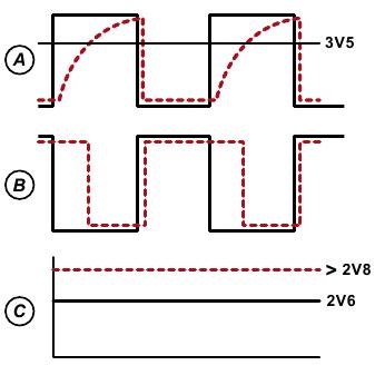
Rice. 2. Oscillograms of signals at different points.
The reference voltage at point D is adjusted once using the divider R4/R5 (by changing the value of R4). The magnitude of this voltage is highly dependent on the surface area of the sensor plate (usually a few square centimeters). Big square The surface of the plate increases capacitance and the voltage at point C will still be greater than when the plates were not touching. The reference voltage at point D should be set closer to 3.4 V. The touch sensor can also work with plates large area(for example, you can use the entire body as a sensor).
The output signal can be used to turn on various loads. In many cases it is recommended to add one Schmitt trigger to the output, especially if the output is connected to a digital input.
Wim Abuys

Rice. 4. The location of the components on the printed circuit board.


Rice. 5. PCB.
Rice. 6. Printed circuit board (mirror view).
Capacitive touch sensor
The main element necessary for the implementation of the system capacitive sensors is a variable capacitor. He must have simple design and sensitivity to touch. Since the sensing element is built as an "open" capacitor, electric field can interact with an external capacitive object, in our case, a finger. Figure 1 shows a top and side view of a capacitive sensor implemented directly on the board.

Rice. one.
As shown in Figure 1, a capacitor forms between the conductive layer and ground. The interaction of the conductive layer and the conductors surrounding it creates a base capacitance, the value of which can be measured. The basic capacitance of such a sensor is about 10 pF. When the conductor, i.e. finger, approaching an open capacitor, as a result of interference electric field, the capacitance of the capacitor changes. Due to the capacitance of the finger, the capacitance of the sensor increases even without being touched. By measuring the capacitance of the sensor and comparing each result with the base capacitance, the microcontroller can determine not only the fact that the button was pressed, but also the sequence of switching on, which is used to implement more complex interfaces, such as sliders.
The sensitivity of the sensor depends on the distance between the conductive and ground layers. The recommended distance is 0.5 mm. In addition, the overall sensitivity of the system depends on the thickness of the board: as the thickness of the board decreases, the sensitivity decreases. The recommended board thickness is 1…1.5 mm.
The sensor capacitance without finger capacitance is about 5…10 pF.
The ground layer under the sensor shields it from other electronic components in the system. It also helps to maintain a constant base capacitance, which is required as a reference for each measurement.
Sensor design and user interface
The complete interface consists of the capacitive sensor itself (implemented on the board) as well as the dielectric between the sensor and the finger when it is touched.
Implementation of a capacitive sensor on a printed circuit board
Capacitive sensor dependencies can be displayed using the example of a conventional flat capacitor. Figure 2 shows its key elements.

Rice. 2.
The term "base capacitance" refers to the capacitance measurement of a sensor that has not been affected in any way. For simplicity, as a base capacitance, we take the capacitance of a capacitor formed by a conductive layer at the top of the printed circuit board and a ground layer at the bottom (bottom and top plates in Figure 2).
The distance d is determined by the printed circuit board. As mentioned earlier, as d decreases, the base capacitance increases and the sensitivity decreases. The specific capacitances of space (e 0) and material (e r) determine the dielectric constant of the board.
Sensor area A is usually limited by the size of the finger, calculated as the average between the finger of a child and an adult. Note that the area of the sensor that is not covered by the finger is useless.
Thus, during the development process, it is necessary to minimize the basic capacitance of the sensor. A condition for good system sensitivity and reliability is to maximize the change in capacitance as the finger approaches the sensor. Of course, these two goals are mutually exclusive: as the sensor area increases to the size of a finger, the base capacitance increases, since it is proportional to A.

Rice. 3.
Figure 3 shows the button and slider layout used as an example in this document.

Rice. 4. Building layers (red - upper signal layer, blue - lower ground layer)
Figure 4 shows four options for placing the sensor on a printed circuit board, which differ in the construction of the ground layer.
Top left shows only the top signal layer: four sensor pads surrounded by the top ground plane; the bottom layer is not used. The upper right side of the figure shows the same board design with 25% ground coverage. Bottom left is the 50% infill version and right is the 100% infill version.
It is recommended to use multiple ground planes under each sensor to isolate the sensor elements from noise and other external changes that could cause a change in base capacitance. Obviously 100% padding, as shown in the left bottom corner Figure 4 provides maximum noise isolation and also increases base capacitance. To obtain the optimal ratio of noise isolation and base capacitance, it is customary to use an infill from 50% to 75%.
Insulating layer of the sensor
In this type of application, the insulating layer of the sensor is made of plastic. Thanks to this layer, the fingers do not come into direct contact with the sensor. The model presented in Figure 2 can be used to visualize the interaction interface between a finger and a capacitor. In this case, the lower lining acts as a sensor, and the upper one acts as the user's finger. It becomes clear that with an increase in the interaction area to the size of a finger, A increases, and the change in capacitance is maximized. As the insulation layer d increases, the change in capacitance decreases inversely. Key moment, which cannot be ignored, is the material from which the insulation is made. The dielectric constant of the insulating material as well as its thickness greatly influence the sensitivity and ease of use of a capacitive touch sensor. Table 1 lists the dielectric constants of some materials.
Table 1. Dielectric constants of materials
In addition to the insulator itself, important point is the connection of the sensor and the insulator. If the connection is loose and there are gaps, the capacitance of the sensor will change. Therefore, adhesive insulators are often used.
Using the MSP430 to Measure the Capacitance of a Touch Sensor
Now consider two methods for measuring the capacitance of the touch sensor.
Oscillator based measurement method
The first method is based on the use of an oscillator. This method can be implemented based on the MSP430, using its comparator and capacitive sensor as a tuning element. Any change in sensor capacitance will result in a change in frequency, which can be measured using Timer_A on the MSP430 microcontroller. Figure 5 shows an example of such a system.

Rice. five.
Resistors R provide support for the comparator when Px.y is set high. This signal is opposite in polarity to the charging or discharging signal of the capacitance of the sensor (C sensor), which leads to long-term oscillations. With equal values of resistance R, the boundary values are 1/3 V cc and 2/3 V cc , the oscillation frequency is calculated by the formula:
fOSC = 1/
By counting the number of periods of oscillation during a given period of time, the frequency can be calculated and the capacitance can be measured. In this application, the resistance of the resistor RC is 100 kΩ. As a result, the oscillation frequency is approximately 600 kHz with a sensor capacitance of 10 pF.
The integrated 12 kHz VLO is used as a clock source. This signal is applied to the watchdog timer WDT. With each watchdog interrupt, the kernel examines the state of the Timer_A timer register, TAR. The difference between the last two register values is calculated. In reality, the absolute value of the capacitance is not needed, only its change is interesting.
It is possible to build a system with several capacitive sensors. This requires the construction of a multiplexer on the comparator Comparator_A + (Figure 6).

Rice. 6.
To implement the system, one resistor is required for each sensor and three resistors for the comparator.
Resistor based capacitance measurement method
The second method for measuring the capacitance of the touch sensor is based on using an external resistor to charge or discharge the capacitive sensor. One of the MSP430 ports is used for charging or discharging, the charge or discharge time is measured using the built-in Timer_A timer. Figure 7 shows an example system using the MSP430 microcontroller to measure the discharge time of a capacitor.

Rice. 7.
With a capacitance value of C sensor = 10 pF and R = 5.1 M, the discharge time is about 250 µs. Px.y is configured as a high level output to charge the capacitor. It can be reconfigured as an input to discharge the C sensor through R. The maximum current through the MSP430 port is ±50 nA.
If the Px.y port supports interrupts (for the MSP430, these are ports P1.x and P2.x), the internal low signal can be used as a threshold at which they are generated. When this interrupt is received, the kernel parses the contents of the Timer_A timer register. The timer can use the internal DCO as the clock source. The frequency of the generated signal is 8 or 16 MHz (depending on the MSP430 family).

Rice. 8.
Figure 8 shows one measuring cycle. The timer starts counting from zero and at the moment when the voltage on the sensor reaches the threshold V IT , the timer value is read. Also, the timer can operate in the constant counting mode, while it is necessary to read its values at the time of the beginning and end of the capacitor discharge and calculate their difference. With an increase in the capacitance of the sensor, the discharge time of the capacitor increases and the number of timer cycles increases during the measurement.
It was said above that one resistor is needed for each port. The circuit can be simplified by using one resistor for two ports. While measuring the capacitance of one of the sensors, the port connected to the second should have a low signal level, i.e. serves as a ground for discharging the capacitance. Another advantage of such a scheme is that the capacitance of each sensor can be measured in two directions: charging from zero to high level and discharging from V cc to a low level threshold. Figure 9 shows this method.

Rice. nine.
The counting of cycles must be done twice: during charging and discharging. At the same time, 50/60 MHz noise has less effect on the measurement result.
Software
After the measurement result is obtained, it must be programmatically interpreted. Power supply noise, clock offset, external 50/60 MHz noise can lead to poor decision making.
Sometimes, for efficiency, you can discard a few low-order bits of the result. This is acceptable if you only want to track the fact that the button was clicked. But if a higher resolution is required, this can no longer be afforded. Low-pass filtering and simple averaging of several results can help smooth out the noise. But to achieve low power consumption, the presence of low bits of the measurement result is more critical.
Sensor Base Capacitance Tracking
Without the ability to dynamically track changes in sensor capacitance, any kind of instabilities can lead to false detection of a button being pressed or “sticky”. Consider a variant with a simple button that has two states: on/off. If the result is shifted, it may approach the threshold at which the button is considered pressed, that is, a false positive will occur.
One method for tracking and adjusting base capacity is shown in Figure 10.
You need to pay attention to the fact that these actions are performed for each sensor separately. Calculation of the variable "Delta" and adjustment of "base" is done differently in RO and RC algorithms. In RO, the measured value decreases as the capacitance of the capacitor increases; and in RC the measured value increases.
After completing the measurement, first of all, it is necessary to determine whether a touch has occurred. This can be done by comparing the obtained value with a threshold corresponding to the lightest touch that can be recognized. If it is determined that there was no touch, the base value is adjusted. How the adjustment takes place depends on the direction in which the change occurred.
As the capacitance measurement increases, it is recommended to adjust the base value more slowly. An increase in the result can mean not only a shift due to errors, but also as a result of the movement of the finger in the direction of the sensor. And if the base value adjusts quickly, the actual touch of the finger may not be noticed. To do this, it is recommended to adjust the base value by only one unit each measurement cycle (Figure 10).

Rice. 10.
Implementing a Regular Button Function
Button building is the most common use case for capacitive sensors. Figure 11 shows an example of building a system with four buttons.

Rice. eleven.
The threshold at which the decision is made that the button is pressed must be higher than the noise.
Slider Function Implementation
A more complex function, organized on capacitive sensors, is a slider. In this case, it is necessary to monitor the excess of several thresholds.
The easiest way to build a slider can be organized if several positions are defined for each sensor. The example below (Figure 12) considers a system where 16 positions are defined for each sensor. The result is a 64-position system.

Rice. 12.
DELTAMAX is the maximum capacitance value that can be reached. Then the range from 0 to DELTAMAX is divided into a certain number of Steps. Zero corresponds to the case when the button is not pressed. The position of the finger is determined by the maximum value. A more linear transfer characteristic of the system is achieved by interpolating the values of all sensors.
Multiplexing sensors to build a slider
When building a slider, it is possible to expand the number of sensors with a limited number of input / output ports by means of multiplexing. In this case, several sensors are connected to one output. Additional sensor only increases the base capacity. However, with an increase in the base capacitance, at the moment of impact on only one of the sensors, the response of the sensor is less. Therefore, it is common not to connect more than two sensors together.
In order to determine which of the multiplexed sensors is affected, they need to be separated in space. An example of the location of sensors in such a system is shown in Figure 13.

Rice. 13.
Conclusion
The article discusses two methods for implementing capacitive touch sensors using the MSP430. Each of the methods has its own advantages and disadvantages. Let's consider the main ones.
- Oscillator based method:
- Requires a microcontroller with Comp_A + comparator;
— The number of independent sensors is limited by the number of Comp_A+ inputs;
- Requires one external resistor R for each sensor, as well as a chain of three R;
— Sensitivity is limited by power consumption (programmable measurement time);
- Resistor based method:
- Can be implemented on any MSP430 microcontroller;
- Up to 16 independent sensors (16 I / O ports working with interrupts);
— One external resistor R for every two sensors;
- Sensitivity is limited by the maximum frequency of the microcontroller (fixed measurement time);
— Minimum energy consumption;
The application can be extended and optimized by the user to implement the end device.
Full description various examples MSP430 applications, program sources, Additional information can be found on the website www.site in the section on microcontrollers.
Obtaining technical information, ordering samples, delivery -
e-mail:
New family of clock generators
Texas Instruments introduced a family programmable clock generators, with 1 to 4 PLL circuits. ICs allow you to generate up to 9 clock signals synthesized from a single input frequency. Each output supports in-system frequency programming up to 230 MHz. These features provide a number of advantages. These include lower power consumption, a faster design process, and the ease of changing clock speeds without having to redesign the system. These advantages will significantly reduce the cost of consumer applications, incl. IP set-top boxes, IP phones, digital media systems (digital TVs, streaming media devices, printers, navigation systems and portable devices).
The new clock generators are optimized to work with DaVinci TM (TI) processors to generate clocks for digital processors, audio ADCs or codecs, and Ethernet or USB controllers. The built-in voltage controlled crystal oscillator (VCXO) allows frequency synchronization of various data streams.
| Composition of the new clock family generators |
||
|---|---|---|
| Name | PLL | Output, V |
| CDCE949 | 4 | 2,5/3,3 |
| CDCE937 | 3 | 2,5/3,3 |
| CDCE925 | 2 | 2,5/3,3 |
| CDCE913 | 1 | 2,5/3,3 |
| CDCEL949 | 4 | 1,8 |
| CDCEL937 | 3 | 1,8 |
| CDCEL925 | 2 | 1,8 |
| CDCEL913 | 1 | 1,8 |