Magnetic bearings. Magnetic bearing with permanent magnets
FOREWORD
The main element of many machines is a rotor rotating in bearings. The growth of rotation speeds and capacities of rotary machines with a simultaneous trend towards a decrease in mass and overall parameters puts forward the problem of increasing the durability of bearing assemblies as a priority. Moreover, in a number of areas modern technology bearings are required that can operate reliably in extreme conditions: in vacuum, at high and low temperatures, ultrapure technologies, in aggressive environments, etc. The creation of such bearings is also an urgent technical problem.
The solution of these problems can be carried out as an improvement of traditional rolling and sliding bearings. and the creation of non-traditional bearings that use other physical principles of action.
Traditional rolling and sliding bearings (liquid and gas) have now reached a high technical level. However, the nature of the processes occurring in them limits, and sometimes makes it fundamentally impossible to use these bearings to achieve the above goals. So, significant shortcomings rolling bearings are the presence of mechanical contact between moving and stationary parts and the need for lubrication of the raceways. There is no mechanical contact in plain bearings, but a system of lubrication is needed to create a lubricating layer and seal this layer. It is obvious that the improvement of sealing units can only reduce, but not completely eliminate the mutual penetration of the lubricant and external environment.
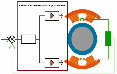
Bearings are free from these disadvantages, in which magnetic and electric fields. Among them, active magnetic bearings (AMPs) are of the greatest practical interest. The work of AMN is based on the well-known principle of active magnetic suspension of a ferromagnetic body: the body is stabilized in a given position by the forces of magnetic attraction acting on the body from controlled electromagnets. The currents in the windings of electromagnets are formed using the system automatic control, consisting of body movement sensors, an electronic controller and power amplifiers powered by an external source electrical energy.
First examples practical use active magnetic suspensions in measuring instruments date back to the 40s of the XX century. They are associated with the names of D. Beams and D. Hriesinger (USA) and O. G. Katsnelson and A. S. Edelstein (USSR). First active magnetic bearing was proposed and experimentally studied in 1960 by R. Sixsmith (USA). wide practical use AMS in our country and abroad began in the early 70s of the XX century.
The absence of mechanical contact and the need for lubrication in AMPs makes them very promising in many areas of technology. These are, first of all: turbines and pumps in vacuum and cryogenic engineering; machines for ultrapure technologies and for operation in aggressive environments; machines and devices for nuclear and space installations; horoscopes; inertial energy storage devices; as well as products for general engineering and instrumentation - grinding and milling high-speed spindles, textile machines. centrifuges, turbines, balancing machines, vibration stands, robots, precise measuring instruments etc.
However, despite the successes, AMJIs are being implemented much more slowly than expected from predictions made in the early 1970s. First of all, this is due to the slow perception of innovations by the industry, including AMS. Like any innovation, in order to be in demand, AMPs need to be popularized.
Unfortunately, at the time of this writing, only one book is devoted to active magnetic bearings: G. Schweitzer. H. Bleulerand A. Traxler "Active magnetic bearings", ETH Zurich, 1994, 244 p., published in English and German. Small in volume, this book is primarily aimed at the reader who is taking the first steps in understanding the problems that arise when creating an AMS. Making very modest demands on the engineering and mathematical background of the reader, the authors build the main ideas and concepts in such a well-thought-out sequence that allows a beginner to easily get up to speed and conceptually master a new area for himself. Undoubtedly, this book is a remarkable phenomenon, and its popularizing role can hardly be overestimated.
The reader may ask whether it was worth writing a real monograph, and not just a translation of the book cited above. First, since 1992 I have been invited to give lectures on the AMS at Russian universities. Finland and Sweden. A book grew out of these lectures. Secondly, many of my colleagues have expressed a desire to have a book on LMP written for developers of AML machines. Thirdly, I also realized that many engineers who do not specialize in AMB at all need a book exploring such a control object as an electromagnet.
The purpose of this book is to equip engineers with the methods of mathematical modeling, synthesis, and analysis of AMPs and thereby promote interest in this new field of technology. I have no doubt that the book will also be useful to students of many technical specialties, especially in course and diploma design. When writing the book, I relied on 20 years of experience in the field of AMB as a scientific director of the research laboratory of magnetic bearings at the Pskov Polytechnic Institute of the St. technical university.
The book contains 10 chapters. Chapter 1 gives short description of all possible types of electromagnetic suspensions, the purpose of which is to broaden the reader's horizons. Chapter 2, aimed at AMB users, introduces the reader to active magnetic bearing technology - it is the history of development, design, characteristics, development problems and a few examples. practical applications. Chapters 3 and 4 provide a method for calculating bearing magnetic circuits. An electromagnet as a control object is studied in Chapter 5. In Chapter 6, the problems of controller synthesis and analysis of the dynamics of a one-stage magnetic suspension are solved. This is a chapter on how to control the gimbal and what can get in the way of getting the dynamic performance you want. The central place is occupied by Chapter 7, which considers the problems of controlling the suspension of a rigid rotor with five degrees of freedom, investigates the interaction of the suspension and the drive motor, and also touches upon the issue of creating bearingless electrical machines. The influence of elastic bending deformations of the rotor on the dynamics of the suspension is discussed in Chapter 8. Chapter 9 is devoted to digital control of the suspension. In the final chapter 10, a number of dynamic aspects related to the implementation of rotor suspensions in AMB are considered.
As for the list of references at the end of the book, I did not try to include in it all the historically significant articles on AML and I ask for forgiveness from those researchers whose contributions to this area are not mentioned.
Since the range of issues is very wide, it was not possible to maintain one system symbols throughout the book. However, each chapter uses permanent system designations.
I am grateful to my teachers, professors David Rakhmilyevich Merknin and Anatoly Saulovitch Kelzon - they greatly contributed to the appearance of this book. I would like to thank my colleagues in the laboratory of magnetic supports and the university, in particular Fedor Georgievich Kochevin, Mikhail Vadimovich Afanasiev. Valentin Vasilyevich Andreen, Sergey Vladimirovich Smirnov, Sergey Gennadyevich Stebikhov and Igor Ivanovich Morozov, whose efforts created many machines with AMB. I also enjoyed the conversations and teamwork with Professor Kamil Shamsuddinovich Khodjaen and Associate Professors Vladimir Alexandrovich Andreev, Valery Georgievich Bogov and Vyacheslav Grigorievich Matsevich. I would also like to note the contribution of graduate students and postgraduate students who worked with me with great enthusiasm in the field of AMS - these are Grigory Mikhailovich Kraizman, Nikolai Vadimovich Khmylko, Arkady Grigoryevich Khrostitsky, Nikolai Mikhailovich Ilyin, Alexander Mikhailovich Vetlntsyn and Pavel Vasilyevich Kiselev. Special mention deserves technical assistance in preparing the manuscript for publication by Elena Vladimirovna Zhuravleva and Andrey Semenovich Leontiev.
I want to thank the Pskov Engineering Company and the Pskov Polytechnic Institute for their help in financing the publication of the book.
Speaking of magnetic bearings or non-contact suspensions, one cannot fail to note their remarkable qualities: no lubrication is needed, there are no rubbing parts, therefore there are no friction losses, an extremely low vibration level, high relative speed, low power consumption, a system for automatically controlling and monitoring the condition of bearings, the ability to sealing.
All these advantages make magnetic bearings the best solutions for many applications: for gas turbines, for cryogenic technology, in high-speed power generators, for vacuum devices, for various machine tools and other equipment, including high-precision and high-speed (about 100,000 rpm), where the absence of mechanical losses, interference and errors is important.
Basically, magnetic bearings are divided into two types: passive and active magnetic bearings. Passive magnetic bearings are made, but this approach is far from ideal, so it is rarely used. More flexible and wider technical capabilities open with active bearings in which a magnetic field is generated alternating currents in the core windings.
How a non-contact magnetic bearing works
The operation of an active magnetic suspension or bearing is based on the principle of electromagnetic levitation - levitation using electric and magnetic fields. Here, the rotation of the shaft in the bearing occurs without physical contact surfaces with each other. It is for this reason that lubrication is completely excluded, and mechanical wear is nonetheless absent. This increases the reliability and efficiency of machines.
Experts also note the importance of having control over the position of the rotor shaft. The sensor system continuously monitors the position of the shaft and provides signals to the automatic control system for precise positioning by correcting the positioning magnetic field stator, - the force of attraction on the desired side of the shaft is made stronger or weaker by adjusting the current in the stator windings of the active bearings.

Two tapered active bearings or two radial and one axial active bearings- allow contactless suspension of the rotor literally in the air. The gimbal control system operates continuously and can be digital or analog. This ensures high holding strength, high load capacity, and adjustable stiffness and damping. This technology allows bearings to operate in low and high temperatures, in vacuum, at high speeds and under conditions of increased sterility requirements.
From the above, it is clear that the main parts of an active magnetic suspension system are: a magnetic bearing and automatic system electronic control. Electromagnets act on the rotor all the time from different sides, and their action is subject to an electronic control system.

The rotor of a radial magnetic bearing is equipped with ferromagnetic plates, on which the retaining magnetic field from the stator coils acts, as a result of which the rotor is suspended in the center of the stator without touching it. Inductive sensors monitor the position of the rotor all the time. Any deviation from the correct position results in a signal that is applied to the controller, so that he, in turn, returns the rotor to the desired position. The radial clearance can be from 0.5 to 1 mm.
A magnetic thrust bearing functions in a similar way. Electromagnets in the form of a ring are fixed on the shaft of the thrust disk. Electromagnets are located on the stator. Axial sensors are located at the ends of the shaft.
To securely hold the rotor of the machine during its stop or at the time of failure of the holding system, safety ball bearings are used, which are fixed so that the gap between them and the shaft is set equal to half that in the magnetic bearing.
System automatic regulation located in the cabinet, and is responsible for the correct modulation of the current passing through the electromagnets, in accordance with the signals from the rotor position sensors. The power of the amplifiers is related to the maximum strength of the electromagnets, the size of the air gap and the response time of the system to a change in the position of the rotor.
Capabilities of non-contact magnetic bearings
The maximum possible rotation speed of the rotor in a radial magnetic bearing is limited only by the ability of the ferromagnetic rotor plates to resist centrifugal force. Typically the peripheral speed limit is 200 m/s, while for axial magnetic bearings the limit is limited by the resistance of the thrust cast steel to 350 m/s with conventional materials.
Depends on the applied ferromagnets and maximum load which a bearing of the corresponding diameter and length of the bearing stator can withstand. For standard materials, the maximum pressure is 0.9 N/cm2, which is less than with conventional contact bearings, however, the load loss can be compensated by high circumferential speed with an increased shaft diameter.
The power consumption of an active magnetic bearing is not very high. Eddy currents account for the greatest losses in the bearing, but this is ten times less than the energy that is wasted when conventional bearings are used in machines. Couplings, thermal barriers and other devices are eliminated, bearings work effectively in vacuum, helium, oxygen, sea water, etc. The temperature range is from -253°C to +450°C.
Relative disadvantages of magnetic bearings
Meanwhile, there are magnetic bearings and disadvantages.
First of all, the need to use auxiliary rolling bearings that can withstand a maximum of two failures, after which they need to be replaced with new ones.
Secondly, the complexity of the automatic control system, which, if it fails, will require complex repairs.
Thirdly, the temperature of the bearing stator winding rises at high currents - the windings heat up, and they need personal cooling, preferably liquid.
Finally, the material consumption of a non-contact bearing turns out to be high, because the bearing surface area must be extensive to maintain sufficient magnetic force - the bearing stator core is large and heavy. Plus the phenomenon of magnetic saturation.

But, despite the apparent shortcomings, magnetic bearings are already widely used, including in optical systems high precision and in laser installations. One way or another, since the middle of the last century, magnetic bearings have been improving all the time.
after watching videos of individual comrades, such as
I decided and I will be noted in this thread. in my opinion, the video is rather illiterate, so it is quite possible to whistle from the stalls.
going through a bunch of schemes in my head, looking at the principle of suspension in the central part in Beletsky's video, understanding how the "levitrnon" toy works, I came to a simple scheme. it is clear that there should be two support spikes on the same axis, the spike itself is made of steel, and the rings are rigidly fixed on the axis. instead of solid rings, it is quite possible to lay not very large magnets in the form of a prism or a cylinder arranged in a circle. The principle is the same as in the well-known toy "Livitron". only instead of the geroscopic moment, which prevents the top from tipping over, we use the "spread" between the stands rigidly fixed on the axis.
Below is a video with a toy "Livitron"
and here is the scheme that I propose. in fact, this is the toy in the video above, but as I said, it needs something that would not allow the support spike to tip over. the video above uses gyro torque, I use two coasters and a spacer between them.
Let's try to justify the work of this design, as I see it:
magnets repel weakness- you need to stabilize these spikes along the axis. here I used this idea: the magnet is trying to push the spike into the area with the lowest field strength, because. the spike has a magnetization opposite to the ring and the magnet itself is annular, where in a sufficiently large area located along the axis, the intensity is less than at the periphery. those. the distribution of the magnetic field intensity in shape resembles a glass - the intensity is maximum in the wall, and minimum on the axis.
the spike should stabilize along the axis, while being pushed out of the ring magnet into the area with the lowest field strength. those. if there are two such spikes on the same axis and the ring magnets are rigidly fixed, the axis should "hang".
it turns out that it is in the zone with a lower field strength that it is most energetically favorable.
After digging around on the Internet, I found a similar design:

a zone with less tension is also formed here, it is also located along the axis between the magnets, the angle is also used. in general, the ideology is very similar, however, if we talk about a compact bearing, the option above looks better, but requires specially shaped magnets. those. the difference between the schemes is that I extrude the supporting part into the zone with less tension, and in the scheme above, the very formation of such a zone ensures the position on the axis.
For clarity of comparison, I redrawn my diagram: 
they are essentially mirror images. in general, the idea is not new - they all revolve around the same thing, I even have suspicions that the author of the video above simply did not look for the proposed solutions 
here it’s practically one to one, if the conical stops are made not solid, but composite - a magnetic circuit + an annular magnet, then my circuit will turn out. I would even say the initial unoptimized idea is the picture below. only the picture above works for the "attraction" of the rotor, and I originally planned to "repulse" 
for the especially gifted, I want to note that this suspension does not violate Earnshaw's theorem (prohibition). the fact is that we are not talking here about a purely magnetic suspension, without a rigid fixation of the centers on the axis, i.e. one axis is rigidly fixed, nothing will work. those. it's about choosing a fulcrum and nothing more.
in fact, if you watch Beletsky's video, you can see that approximately the same configuration of fields is already used everywhere, the only thing missing is final touch. the conical magnetic circuit distributes the "repulsion" along two axes, but Earnshaw ordered the third axis to be fixed differently, I did not argue and mechanically fixed it rigidly. why Beletsky did not try this option, I do not know. in fact, he needs two "livitrons" - fix the stands on the axis, and connect them to the tops with a copper tube.
you can also notice that you can use tips from any sufficiently strong diamagnet in place of a magnet of polarity opposite to the magnetic support ring. those. replace the magnet + conical magnetic circuit bundle, just with a diamagnetic cone. fixation on the axis will be more reliable, but diamagnets do not differ in strong interaction and high field strengths and a large "volume" of this field are needed in order to apply this at least somehow. due to the fact that the field is axially uniform relative to the axis of rotation, there will be no change in the magnetic field during rotation, i.e. such a bearing does not create resistance to rotation.
logically, such a principle should also be applicable to plasma suspension - a patched "magnetic bottle" (corktron), what will we wait and see.
why am i so sure of the result? well, because it cannot but exist :) the only thing that may have to be made magnetic circuits in the form of a cone and a cup for a more "rigid" field configuration.
well, you can also find a video with a similar suspension:
here the author does not use any magnetic circuits and uses the emphasis on the needle, as is generally necessary, understanding Earnshaw's theorem. but after all, the rings are already rigidly fixed on the axis, which means you can spread the axis between them, which is easily achieved using conical magnetic cores on magnets on the axis. those. until the "bottom" of the "magnetic glass" has been pierced, it is more and more difficult to push the magnetic circuit into the ring. the magnetic permeability of air is less than that of the magnetic circuit - a decrease air gap will increase the field strength. those. one axis is rigidly fixed mechanically - then the supports on the needle will not be needed. those. see the very first picture.
P.S.
here's what I found. from the series, a bad head does not give repentance to hands - the author is still Biletsky - mother don’t cry there - the configuration of the field is quite complex, moreover, it is not uniform along the axis of rotation, i.e. during rotation, there will be a change in the magnetic induction in the axis with all sticking out ... pay attention to the ball in the ring magnet, on the other hand, the cylinder in the ring magnet. those. man stupidly screwed up the suspension principle described here.
well, or soldered the suspension in the photo, i.e. the peppers in the photo use supports on the needle, and he hung a ball in place of the needle - oh shaitan - it worked - who would have thought (I remember they proved to me that I didn’t understand Earnshaw’s theorem correctly), but apparently it’s not crazy to hang two balls and use only two rings enough. those. the number of magnets in the device on the video can be easily reduced to 4, and possibly up to 3 i.e. a configuration with a cylinder in one ring and a ball in the other can be considered experimentally proven to work, see the drawing of the original idea. there I used two symmetric stops and a cylinder + cone, although I think that the cone that part of the sphere from the pole to the diameter work the same.
therefore, the emphasis itself looks like this - this is a magnetic circuit (i.e. iron, nickel, etc.) it’s just
a magnet ring is laid. the reciprocal part is the same, just the other way around :) and two stops work in the thrust - comrade  Earnshaw forbade work on one stop.
Attention!!!
You have disabled JavaScript and Cookies!
You need to enable them for the site to work properly!
Active magnetic bearings
Active magnetic bearings (AMP)
(manufactured by S2M Société de Mécanique Magnétique SA, 2, rue des Champs, F-27950 St.Marcel, France)
|
|
The main areas of application of active magnetic bearings are as part of turbomachines. The oil-free concept in compressors and turbo-expanders makes it possible to achieve highest reliability also due to the absence of wear of machine components. Active magnetic bearings (AMPs) are increasingly being used in many industries. Non-contact active magnetic bearings are used to improve dynamic performance, increase reliability and efficiency. |
|
The principle of operation of magnetic bearings is based on the effect of levitation in a magnetic field. The shaft in such bearings literally hangs in a powerful magnetic field. The sensor system constantly monitors the position of the shaft, and sends signals to the stator position magnets, correcting the force of attraction from one side or another. |
|


1 . general description AMP systems
Active magnetic suspension consists of 2 separate parts:
Bearing;
Electronic control system
The magnetic suspension consists of electromagnets (power coils 1 and 3) that attract the rotor (2).

AMP components
1. Radial bearing
The radial bearing rotor, equipped with ferromagnetic plates, is held by magnetic fields generated by electromagnets located on the stator.

The rotor is transferred to a suspended state in the center, not in contact with the stator. The position of the rotor is controlled by inductive sensors. They detect any deviation from the nominal position and provide signals that control the current in the electromagnets to return the rotor to its nominal position.
4 coils placed along the axes V and W , and offset at an angle of 45° from the axes X and Y , hold the rotor in the center of the stator. No contact between rotor and stator. Radial clearance 0.5-1mm; axial clearance 0.6-1.8 mm.
2. Thrust bearing
A thrust bearing works in the same way. Electromagnets in the form of a non-removable ring are located on both sides of the thrust disk mounted on the shaft. Electromagnets are fixed on the stator. The thrust disc is pushed onto the rotor (eg shrink fit). Axial encoders are usually located at the ends of the shaft.


3. Auxiliary (safety)
bearings
Auxiliary bearings are used to support the rotor when the machine is stopped and in the event of failure of the AMP control system. Under normal operating conditions, these bearings remain stationary. The distance between the auxiliary bearings and the rotor is usually half the air gap, however, if necessary, this can be reduced. The auxiliary bearings are mainly solid lubricated ball bearings, but other types of bearings such as plain bearings can be used.
4. Electronic control system

The electronic control system controls the position of the rotor by modulating the current that passes through the electromagnets depending on the signal values of the position sensors.
5. Electronic processing system signals
The signal sent by the encoder is compared with a reference signal that corresponds to the nominal position of the rotor. If the reference signal zero, the nominal position corresponds to the center of the stator. When changing the reference signal, it is possible to move the nominal position by half the air gap. The deflection signal is proportional to the difference between the nominal position and the position of the rotor in this moment. This signal is transmitted to the processor, which in turn sends a corrective signal to the power amplifier.
Ratio of output signal to deviation signalis determined by the transfer function. The transfer function is chosen to maintain the rotor with maximum accuracy in its nominal position and to quickly and smoothly return to this position in the event of interference. The transfer function determines the stiffness and damping of the magnetic suspension.
6. Power amplifier
This device supplies the bearing electromagnets with the current necessary to create a magnetic field that acts on the rotor. The power of the amplifiers depends on the maximum strength of the electromagnet, the air gap and the reaction time of the automatic control system (ie the speed at which this force must be changed when it encounters an obstacle). The physical dimensions of the electronic system are not directly related to the weight of the rotor of the machine, they are most likely related to the ratio of the indicator between the amount of interference and the weight of the rotor. Therefore, a small shell will suffice for a large mechanism equipped with a relatively heavy rotor subject to little interference. At the same time, a machine that is subject to more interference must be equipped with a larger electrical cabinet.
2. Some characteristics of the AMP
Air gap
The air gap is the space between the rotor and the stator. The amount of clearance indicated e, depends on the diameter
As a general rule, the following values are used:
|
D (mm) |
e(mm) |
|
< 100 |
0,3 - 0,6 |
|
100 - 1 000 |
0,6 - 1,0 |
Rotational speed
The maximum rotation speed of a radial magnetic bearing depends only on the characteristics of the electromagnetic rotor plates, namely the resistance of the plates to centrifugal force. With standard inserts, circumferential speeds of up to 200 m/s can be achieved. The speed of rotation of the axial magnetic bearing is limited by the resistance of the cast steel of the thrust disc. A peripheral speed of 350 m/s can be achieved using standard equipment.
The load of the AMB depends on the ferromagnetic material used, the diameter of the rotor and the longitudinal length of the suspension stator. Maximum specific load AMP made from standard material is 0.9 N/cm². This maximum load is lower than the corresponding values of classical bearings, however, the high peripheral speed allows the shaft diameter to be increased in order to obtain the maximum large surface contact and therefore the same load limit as for a classic bearing without the need to increase its length.
Power consumption
Active magnetic bearings have very low power consumption. This energy consumption comes from hysteresis losses, eddy currents (Foucault currents) in the bearing (power taken on the shaft) and heat losses in the electronic shell. AMPs consume 10-100 times less energy than classical ones for mechanisms of comparable size. The energy consumption of the electronic control system, which requires external source current is also very low. Batteries are used to maintain the gimbal in the event of a mains failure - in this case, they turn on automatically.
Ambient conditions
AMB can be installed directly in the operating environment, completely eliminating the need for appropriate couplings and devices, as well as barriers for thermal insulation. Today, active magnetic bearings operate in a wide variety of conditions: vacuum, air, helium, hydrocarbons, oxygen, sea water and uranium hexafluoride, as well as at temperatures from - 253° C to + 450 ° FROM.
3. Advantages of magnetic bearings
- Non-contact / liquid-free
- no mechanical friction
- lack of oil
- increased peripheral speed - Improving Reliability
- operational reliability of the control cabinet > 52,000 h.
- operational reliability of EM bearings > 200,000 h.
- almost complete absence preventive maintenance - Smaller turbomachine dimensions
- no lubrication system
- smaller dimensions (P = K*L*D²*N)
- less weight - Monitoring
- bearing load
- turbomachine load - Adjustable parameters
- active magnetic bearing control system
- stiffness (varies depending on the dynamics of the rotor)
- damping (varies depending on rotor dynamics) - Operation without seals (compressor and drive in a single housing)
- bearings in process gas
- wide operating temperature range
- optimization of the rotor dynamics due to its shortening
The indisputable advantage of magnetic bearings is the complete absence of rubbing surfaces, and, consequently, wear, friction, and most importantly, the absence of working area particles generated during the operation of conventional bearings.
Active magnetic bearings feature high load capacity and mechanical strength. They can be used at high rotational speeds, as well as in vacuum and at various temperatures.
Materials provided by S2M, France ( www.s2m.fr).
The magnetic bearing, like the rest of the mechanisms of the bearing group, serves as a support for the rotating shaft. But unlike common rolling and plain bearings, the connection to the shaft is mechanically non-contact, that is, the principle of levitation is used.
Classification and principle of operation
Using the principle of levitation, the rotating shaft literally soars in a powerful magnetic field. To control the movement of the shaft and coordinate the operation of the magnetic installation allows a complex system sensors, which constantly monitors the state of the system and gives the necessary control signals, changing the force of attraction from one side or another.
Magnetic bearings are divided into two large groups- active and passive. More details about the device of each type of bearing below.
- Active magnetic bearings.

1, 3 - power coils; 2 - shaft Distinguish between radial and thrust mechanisms (according to the type of perceived load), but their principle of operation is the same. A special rotor is used (a regular shaft will not work), modified with ferromagnetic blocks. This rotor "hangs" in a magnetic field created by electromagnetic coils that are on the stator, that is, around the shaft 360 degrees, forming a ring.
An air gap is formed between the rotor and the stator, which allows the parts to rotate with minimal friction.

The depicted mechanism is controlled by a special electronic system, which, using sensors, constantly monitors the position of the rotor relative to the coils and, at the slightest shift, supplies a control current to the corresponding coil. This allows the rotor to be kept in the same position.

The calculation of such systems can be studied in more detail in the attached documentation.
- Passive magnetic bearings.

The rotor is equipped with a permanent magnet in the same way as the stator, which is located in a ring around the rotor. Poles of the same name are located side by side in the radial direction, which creates the effect of shaft levitation. Such a system can even be assembled by hand.
Advantages
Of course, the main advantage is the absence of mechanical interaction between the rotating rotor and the stator (ring).From this it follows that such bearings are very durable, that is, they have increased wear resistance. Also, the design of the mechanism allows it to be used in aggressive environments - high / low temperature, aggressive air environment. Therefore, MFs are increasingly being used in the space industry.
disadvantages
Unfortunately, the system has big amount shortcomings. These include:- Difficulty in controlling active suspensions. A complex, expensive electronic gimbal control system is required. Its use can be justified only in the "expensive" industries - space and military.
- The need to use safety bearings. A sudden power outage or failure of the magnetic coil can lead to catastrophic consequences for the entire mechanical system. Therefore, for insurance, together with magnetic bearings, mechanical bearings are also used. In the event of a failure of the main ones, they will be able to take on the load and avoid serious damage.
- Coil winding heating. Due to the passage of a current that creates a magnetic field, the winding of the coils heats up, which is often an unfavorable factor. Therefore, it is necessary to use special cooling units, which further increases the cost of using the gimbal.
Areas of use
The ability to work at any temperature, in vacuum and lack of lubrication allows the use of suspensions in the space industry, in oil refining industry machines. They also found their application in gas centrifuges for uranium enrichment. Various power plants also use maglevs in their generating sets.
Below are a few interesting videos on this topic.