Is it possible to use the pass switch as a normal one. Connecting a pass-through switch with your own hands
A. Zemskov posted the video. Not ideal, but leaves a feeling of complete understanding of the topic within the framework of the material taught by the author. Of course, there were those who left rude remarks like: things are called switches, they throw the ends of the chains crosswise. Readers understand that critics are driven by envy. Today we will discuss how to connect a pass-through switch.
Pass-through switch operation
Passage switch Legrand costs 500 rubles. For convenience. Passage switches indulge in those who want to live luxuriously. Let's bring typical example A. Zemskova - the person brought a lot to our knowledge on a variety of topics. We have a long corridor leading from the bedroom to the kitchen, bypassing the toilet. It is clear that I wanted to go to the refrigerator at night, not to wake up the sleepers with the noise, go back, go to the toilet on the way back. wish constant help top lighting. Even if someone decides to turn off the lights.
Absurd? Not at all. Take a look at the drawing. Let's say:
- One switch is in the kitchen area, the second - near the bedroom. There is a long corridor between them.
- One light bulb. Occupies the center of a straight ceiling. Let's say in advance that it is possible to make wiring for an arbitrary amount.
- Attention! Three options. Let's discuss.
Switching schemes
Two simple switches
Whatever one may say, it is not possible to provide the task to be performed with two ordinary switches. They tear one chain, both at once, the matter does not change. In the first case, the phase opens, in the second - there is no difference how to connect. To turn on the light, you need to close both switches. We can disturb the kitchen by turning on the corridor light beforehand, the household is unlikely to like the execution. The issue of saving electricity is not acute, let's put it aside, the main trouble, one trouble does not come:
- The switch is located in the middle of the corridor, by the front door. It is not possible to use it from the side of the bedroom, kitchen, bathroom.
- Maybe you need to turn on the light from the other end. Let's say someone turns it off if the key is covered in darkness and it's hard to find. It is very important for children, they are usually afraid to leave the room at night.
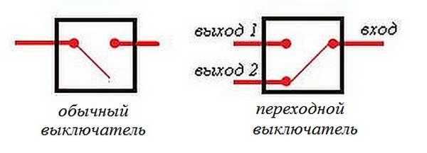
Typical breaker vs walk-through
The pass switch toggles the working contact between the output. Painted the veins different colors. It is perfectly visible: at a certain neutral position, the phase is short-circuited. We get a fire, knocked out traffic jams, a bunch of nerves, experiences. Remember a simple rule: avoid putting a pass switch in the same circuit as a standard one. Available, one working scheme using a toggle switch, we will consider later (you can see the second option in advance in figure number 2).

When solving the issue of three control points for the illumination of the corridor. Throws the wiring crosswise, creating curious possibilities for organizing an infinite number of switches. Please note: despite the manipulation of the neutral, phase, it is not possible to create short circuit. The pass switch is used in tandem with a simple one. Let's describe the structure:
- The world is extinguished. A simple switch broke one wire.
- Leaving the bedroom to the kitchen, turn on the illumination, closing the contact.
- Then we calmly go to the refrigerator (horizontal bar, toilet bowl).
- Feeling the threshold of the kitchen, we throw the switch through, it simply changes the polarity of the phase, the neutral of the light bulb.
Now there are many people who say: the option is unsuitable. We will answer: if the power was direct current, it is often found on ships, in cars, trains, it would work. It is worth putting a diode in the right place. With regards to a typical apartment, the combination does not look the best.
Walk-through switches work in pairs
Take a look at the third option, it is drawn how to use the pass-through switches. Note that there are two wires running between the control points. A big minus for those who expect to manage using old veins lying in the thickness of the walls. Look, you can see: the neutral (black wire) goes to the chandelier. The neutral can be broken, connected at any time from both ends of the corridor. There is a phase on one wire, you just need to apply it to the desired point. The problem is being solved.

Now we leave the bedroom, turn on the light, get to the threshold of the kitchen, turn off the chandelier. By the way, if anyone wants to join the night gatherings, he will solve problems in the same manner. Suppose we wanted to place another switch - say - near the front door.
Toggle switches paired with walk-throughs
Take a look at figure number two: the third 3-point wiring diagram is shown. Something new is presented. The toggle switch is called double, cross. Take a closer look, you can see: it consists of two parts. Each individually will be a pass-through switch. Allows the use of a two-button walk-through switch in order to organize a third control point. Only the keys must be pressed synchronously.
There are three images. The first offers to see the result of turning on the toggle switch in pairs. Actually, inoperable, the polarity of the lamp voltage changes. There is no point in messing around with diodes for someone who has found money to throw it away by buying a couple of toggle switches. The cost is considerable. It is permissible to move on to the third option, the second was considered above.
Correct connection of the toggle switch for organizing three lighting control points
A one-button walk-through switch in the amount of two pieces is combined with a toggle switch. The drawing uses two colors. Imagine the phase is on the blue loop as shown in the picture. It's time to go visit. We turn off the light with one movement of the toggle switch.
Other options work similarly. Now the light in the corridor will be able to turn on, turn off any of the three points. Entrance door, kitchen threshold, bedroom exit. Toggle switches are recruited in garlands. Turn on towards each other.
Thus, we get the second rule. For toggle and feed-through switches: the switches are switched towards.
We believe it is unnecessary to explain the words. It can be clearly seen in the first figure, where the switches are located side by side to each other. The second looks outward, towards the power supply and the chandelier light bulb.
Do-it-yourself pass-through switch: labor lesson
Looking into electronic catalogs, noticed, a triple pass switch costs a round sum. The age-old Russian question of poverty, reinterpreted by Shakespeare: to be or not to be. We chose the first one: a rare midnight glutton is definitely capable of paying money for walk-through switches. We present to the attention of readers the first handmade in Runet, it will really be shown how to convert a simple switch costing around a hundred (a really cheap model) into an expensive thing - a pass-through switch. And without special skills, special techniques.
We look at the first picture, we see the switch, the buttons are removed. The case is removed from the socket. The picture shows: typical wiring diagram, 2 keys. Colored lines show, signed screws of spacers of the socket box, clamping contacts of suitable wires. It is necessary to significantly loosen the fasteners to remove the switch from the socket. Take the trouble to turn off the power beforehand, we strongly recommend checking the location of the phase with a probe, draw the places along the cambric (plastic insulation of the core). Makes the process extremely easy reverse installation switch.

Breaker screws

Now we look at the next picture: the reverse side of the future victim is shown. We see the clamps of the switch body, which should be unbent, removing the electrical part. It is done with a standard screwdriver in a few minutes. Then we take out the spring pushers from the plastic frame. Easier to do with a thick slotted screwdriver. Thin just won't fit. You will quickly understand. Avoid haste, the most difficult place in the process of reworking a cheap switch in the entrance. In the picture, the spring pushers are removed, moving contacts are visible.

We missed the moment of removing the plastic part from the ceramic (in the pictures), the simplest process does not require explanation. The ends of the removed part of the switch contain two weak teeth. Just pry with a slotted screwdriver, let's start altering simple switch in the entrance. Now on the ceramic we see groups of contacts:

Contact groups
- contact pads general group.
- Individual contacts for each bulb.
- Movable rocker contacts.

It remains to turn one rocker 180 degrees, cut off the contact area of \u200b\u200bthe general group (it is better not to isolate). The resulting position is shown in the last image. Now the final stage - how does it all work!? We take both buttons, glue them together with a Chinese gun to become a single whole (or replace it with a single switch button). One contact is closed - the second will hang in the air.
Genius is simple. Now readers know how to make a pass-through switch from a simple one, let's add: in principle, it is not necessary to remove spring pushers. Let's do without it. Two buttons do not have to be glued if you remove the key of a conventional switch of the same width, from the previous manufacturer. The pinout of the legs is preserved. It will allow you to make a pass-through switch with your own hands, to produce a workable, beautiful product.
We consider that we have considered questions asked. They showed how to connect the pass switch correctly, how not to do it, told how to save good money. We hope that the recommendations will be to your liking, the handy owner will be able to boast of having a house original design — pass-through switch.
Lighting control from two places is not a new idea, but it is actively used today. For its implementation, pass-through switches are used.
What is the difference between a switch and a normal switch?
If you look at the passage switch from the side, then no external differences you won't find. The essential and only difference between such switches and simple ones lies inside their design.
For an ordinary single-pole single-gang switch the design has two contacts, fixed and movable. The moving contact is driven by a key that we press by hand and closes with the fixed contact. This closes the electrical circuit and supplies power to the lamp. There are also designs of bipolar single-gang switches that essentially perform the same function as the previous one. Its difference lies in the fact that the zero core going to the lamp breaks similarly to the phase one. This was done to improve security.
Picture 1. circuit diagram connection of single-pole and double-pole single-gang switches
The feed-through switch has two fixed and one moving contacts. The movable contact is always closed with one of the fixed ones. When a key is pressed and it is moved from one position, for example, "off" to another position - "on", the movable contact also changes its position, opening with a closed contact and closing with an open one. That is, the pass-through switch does not have an “off” position and it does not work as a switch, but as a switch. Therefore, in the technical literature and in the catalogs of manufacturers, it is correctly called a switch. For example: "single-pole, single-gang, two-way switch." Keep this in mind when you buy switches for assembling a control circuit from two places.
In addition to single-pole switches, there are two-pole and even three-pole switches.
For ease of understanding, in this article we will use the expression not a switch, but a pass-through switch, since it is more often used among people.
Where is this lighting control system used?
The most commonly considered lighting control system is used in public and industrial premises, namely: in long corridors, tunnels, walk-through rooms, that is, in rooms where there are two doors equally serving as an entrance and exit, in flights of stairs and other places. In all of these cases, walk-through switches are installed next to the doors.
If we talk about residential premises, then the installation location of the walk-through switches can be, for example, Entrance door into the room and place on the wall next to bedside table. In this case, the person entering the room will turn on the light by pressing the pass switch located next to the door, and sitting on the bed, without getting up, will be able to turn it off with the second pass switch located next to the bed.
With the help of pass-through switches, you can control both one lamp or lamp, and their group. For each case apply different types pass-through switches (single-key, two-key, three-key). The main goal pursued by a person by installing such switches is the convenience of controlling the light and reducing energy costs.
Connecting a single-gang switch
Figure 2 shows a schematic diagram of the connection of feed-through switches designed to control one lamp or one group of lamps from two places remote from each other. As you probably already understood, a single-pole feed-through switch has two fixed and one changeover contact. Supply voltage is applied to the changeover contact of one of the switches. The changeover contact of the second switch is connected to the lamp, and the lamps, in turn, to the neutral wire of the mains. The fixed contacts of the first switch will be connected by two separate conductors to the two fixed contacts of the second switch.

Figure 2. Schematic diagram of connecting a through switch with one pole and one key
In the diagram, the position of the changeover contacts of both switches is the same, which corresponds, for example, to the lowered position of their keys. The electrical circuit is then open. If we press the key of the first switch and move it to the raised position, then the changeover contact of this switch, respectively, will also change its position and close electrical circuit. The chain will flow electricity(the direction of current is shown by arrows), and the lamp will start to glow. If you now press the key of the second switch and also change its position, the circuit will again be open and the lamp will go out.
For a more visual representation of how the conductors are connected, Figure 3 shows the wiring diagram for connecting the feed-through switches. The green circle is nothing more than a junction box, inside which the wires are connected. The round pieces inside the box are soldered wires, made in the form of twists with welding, crimped with self-clamping insulating caps, connected by terminals or a screw connection. Everything else I think is clear.

Figure 3 Wiring diagram connection of single-pole single-gang switches
Figure 4 below shows the layout of the equipment and wiring. The connection of wires in this case is carried out in two junction boxes. 1 installed above the walk-through switches 3 . This was done to save wires. In the case of installing one junction box and assembling the circuit in it, in addition, two more wires would have to be laid from the box to the switch closest to us. If the supply wires were supplied from the side of the lamp 2 , then all connections could be made in one box without extra costs wires.
Here: L- linear (phase) wire; N- neutral wire; PE- ground wire.
Figure 4. An example of a lighting control scheme from two places using single-pole single-gang switches
For a better understanding of what you read, I advise you to watch the following video:
Connecting a double-gang switch
The electrical circuit of a double-pole double-gang switch is similar to the electrical circuit of a single-pole single-gang switch. The difference is that one more set of contacts is built into one housing (one more movable and two fixed contacts). Externally, the double-gang switch is similar to a regular double switch.
The purpose of two-button walk-through switches is to divide one large group of lamps or fixtures into two groups. That is, their work is similar to that of a conventional double switch installed in the living room and designed to turn on the lamps of a large beautiful chandelier.
The two-gang switch is connected in accordance with the circuit diagram shown in Figure 5. The directions of the currents are indicated by arrows.
Figure 5. Schematic diagram of connecting a double-gang switch

Figure 6. Wiring diagram for connecting two-pole two-button switches
Lighting control from three or more places
There are times when it becomes necessary to turn on the light in the room not from one or two places, but from three, four or more. To implement such a scheme, manufacturers produce intermediate switches (switches). An example of a control scheme from three places is shown in Figure 7.
Figure 7. Schematic diagram of the connection of two-pole two-button feed-through and intermediate switches
As can be seen from the diagram, the intermediate switch has four fixed and two moving contacts. When a key is pressed, the moving contacts simultaneously switch from one pair of fixed contacts to another pair.

Figure 8. Wiring diagram for connecting single-pole single-gang switches and an intermediate switch
In order to be able to turn the light on and off, for example, from four places, another intermediate switch is installed. It is placed between one of the pass-through switches and the existing intermediate switch. By analogy, you can increase the number of control places to any value.

Figure 9. Schematic diagram of lighting control from five places
Prices for housing and communal services are increasing every year, which makes us think about saving, including electricity. Moreover, this applies to those places about which earlier man didn't even think about it. For example, lighting stairs and landings in high-rise buildings. In the recent past, when electricity prices were miserable, stairs were illuminated 24 hours a day. This problem is also relevant in private houses with more than one floor connected by a staircase. To save money, the light has to be turned off, but for this you need to either go down the stairs again or go up it. This is extremely inconvenient, so sometimes they simply do not turn it off and it burns until the morning, when it becomes light.
For the convenience of lighting in such areas, the so-called "pass-through" switches were developed. They are also called "duplicate" or "flip". They can be distinguished from classic switches by the presence more contacts. Therefore, in order to connect them, you need to know the circuit, and even more so, be able to understand the principle of their operation. Naturally, this is not entirely simple, but absolutely real.
On the key of the pass-through switch there are two arrows (not large), directed up and down.
 This type has a one-button switch. There may be double arrows on the key.
 The connection diagram is not much more complicated than the connection diagram of a classic switch. The difference is only in a larger number of contacts: a conventional switch has two contacts, and a pass-through switch has three contacts. Two out of three contacts are considered common. In the lighting switching circuit, two or more similar switches are used.
 Differences - in the number of contacts
 The switch works in the following way: when switching with the key, the input is connected to one of the outputs. In other words, the feed-through switch is designed for two operating states:
- Input connected to output 1;
- Input connected to output 2.
It has no intermediate positions, therefore, the circuit works as it should. Since there is a simple connection of contacts, according to many experts, they should have been called "switches". Therefore, the transitional switch can be safely attributed to such devices.
In order not to be mistaken what kind of switch, you should familiarize yourself with the switching circuit, which is present on the switch body. Basically, the circuit is available on branded products, but you will not see it on inexpensive, primitive models. As a rule, the circuit can be found on switches from Lezard, Legrand, Viko, etc. As for cheap Chinese switches, there is basically no such circuit, so you have to call the ends with the device.

As mentioned above, in the absence of a circuit, it is better to call contacts at different key positions. This is also necessary in order not to mix up the ends, since irresponsible manufacturers often confuse the terminals during the production process, which means that it will not work correctly.
To ring the contacts, you must have either a digital or pointer device. The digital device should be switched to dialing mode with the switch. In this mode, short-circuited sections of electrical wiring or other radio components are determined. When the ends of the probes are closed, the device emits a sound signal, which is very convenient, since there is no need to look at the device display. If there is a pointer device, then when the ends of the probes are closed, the arrow deviates to the right until it stops.
In this case, it is important to find a common wire. For those who have the skills to work with the device, there will be no particular problems, but for those who picked up the device for the first time, the task may not be solvable, despite the fact that only three contacts need to be sorted out. In this case, it is better to first watch the video, which clearly explains, and most importantly shows how to do it.
Wiring diagram for two pass switches
Such a scheme can be of great help in organizing lighting on the stairs (in two-story house), in a long corridor or in a walk-through room. It can be quite convenient to arrange lighting in the bedroom when one switch is installed at the entrance to the bedroom, and the other next to the bed. In this case, you do not have to constantly get out of bed to turn off the main light.
 Wiring diagram for two walk-through switches
 The connection diagram is very simple and understandable: a phase is applied to the input of one of the switches, the input of the other switch is connected to one of the wires of the chandelier (lamp). The second end of the lamp is connected directly to the neutral wire. The N1 outputs of both switches are connected together, as are the N2 outputs.
The circuit functions quite simply. If you look at the diagram, then in this position the light source is turned on. At the subsequent switching of any of the switches, in random order, the lamp will either turn off or turn on.
In order to make it more clear, you should carefully look at the figure.
 Wiring between two switches.
 In the case of installing such switches indoors, the wiring should be done as shown in the figure below. Modern requirements allow wiring at a distance of 15 cm from the ceiling. As a rule, the wires are placed in special trays or boxes, and the ends of the wires are concentrated in mounting (junction) boxes. This approach has undeniable advantages. The main thing is that a damaged wire can always be replaced. Connection of wires in mounting boxes is carried out using special clamps (contact blocks). At the same time, twists are also allowed, which are then necessarily soldered and reliably isolated.
The output of the second switch is connected to one of the conductors leading to the lighting lamp. The white conductors are the wires connecting the outputs of both switches.
 Wiring in residential area
 How the ends of the wires are connected in the junction box can be found out by watching the corresponding video.
Three-point lighting control option
If there is a need for remote control of the lamp from three places, then you will also have to purchase a cross switch. It switches not one, but two contacts at a time, so it has two inputs and two outputs.
How to connect all three switches can be seen in the figure. This is somewhat more complicated than the previous case, but you can understand the principle of operation.
 Electric circuit for turning on a lamp from three places.
 To connect an electric light source, according to this scheme, you must do the following operations:
- The neutral wire is connected to one of the lamp wires.
- The phase wire is connected to the input contact of one of the feed-through switches.
- The free wire of the lamp is connected to the input contact of the second switch (through).
- The two output contacts of the pass switch are connected to the two input contacts of the cross switch.
- Two output contacts of the second pass switch connected to the two output contacts of the cross switch.
The diagram is the same, but it is shown more clearly where exactly to connect the wires.
 What terminals are the wires connected to.
 Approximately so it is necessary to spread the wires around the room.

Based on the scheme for three control points, it is possible to assemble schemes for 4 or 5 points. In such cases, it is necessary to increase the number of cross switches. They should always be installed between two feed-through switches.
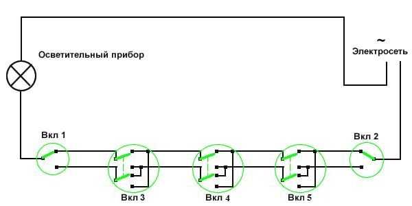 Scheme of organization on / off the lamp for 5 points.
 If one of the cross switches is removed from this circuit, then a 4-point option will be obtained, and if one cross switch is added to it, then a 6-point option will already come out.
Two-gang pass-through switch: wiring diagram
In order to control the operation of two lamps from several points, there are two-button walk-through switches. They have six contacts. The main thing is to identify common contacts. They are determined according to the same principle as when searching for a common contact in single-gang switches.
In a circuit that uses two two-button walk-through switches, much more wires are used.
The phase wire is fed to the inputs of both switches, and the other inputs of the switches are connected to one of the ends of one and the other lamp. The free ends of the lamp are connected to the neutral conductor. The two outputs of one switch are connected to two outputs of the second switch, and the other two outputs of this switch are connected to the other two outputs of the first switch.
The pass-through switch significantly expands the possibilities for users to control lighting fixtures. The design and connection diagram of the pass-through switch allow you to control one lighting fixture or a group of fixtures from several places. It is widely used in buildings, individual rooms and facilities for various purposes with large areas.
Using walk-through switches in the house
Having walk-through switches at different ends of the stadium, concert hall or other large facilities, you can turn on all the lights at the entrance. If you need to leave the building on the opposite side, you do not need to return to the switch that turned on the light - there is the same pass-through switch at the other exit. Electrical circuits with pass-through switches allow you to control the lighting from several different locations.
It is very convenient to use such electrical circuits in underground passages, tunnels, more and more often circuits with walk-through switches are used in private houses and on flights of stairs at the entrances of multi-storey buildings.
Design and principle of operation
Pass-through switch for appearance no different from ordinary products. The big difference is in the design. contact group, which is hidden inside the case. A simple switch closes and opens an electrical circuit on a single wire. The wiring diagram of the pass switch, when the position of the keys is changed, opens one circuit and immediately closes the other. The principle of switching the contacts of the circuit ensures that the switches work in pairs to control the same light source. By technical solution it would be correct to call such an element in the circuit not a pass-through switch, but a switch. Professional terminology has already taken shape, and changes can only bring more confusion, so everything remains as it is.
When the contacts of the pass-through switch are flipped, one section of the lighting circuit is opened, and another is closed. The wiring diagram of the pass switch is changed so that any of the switches is ready to turn the light on or off. The pass switch can only be used in conjunction with another. In practice, it is possible to connect a pass-through switch to the circuit so that it works as a simple one, but then the meaning of all elements of its design is lost.
Kinds
Like conventional switches, walk-through switches are divided depending on the type of wiring: for external wiring, for hidden wiring.
By design contact terminals: terminals with screw clamps, spring clamp terminals.
By number of keys:
- single-key;
- two-key;
- three-key.
They have everything like ordinary switches, the difference is in the design and operation of the contact group. The principle of a single-gang pass-through switch is to switch the input contact to one of the two output contacts. , as well as three-key ones, in their case they contain 2 or 3 designs of the contact group of a single-key switch.
Connecting the pass-through switch is simple, you can do everything yourself. The number of contacts, keys, sizes of switches change, the principle of operation remains the same.

Scheme of the structure of one-, two-, and three-gang switches
- a single-key switch has one input terminal and two output terminals;
- two-key switch - two input terminals and four output terminals;
- three-key switch - three input terminals and six output terminals.
Lighting control from 2 places
One luminaire or a group of luminaires can be controlled from two places: it can be sconces in the corridor or lampposts along garden path. You will need the usual circuit for connecting a pass-through switch, more precisely with two pass-through single-gang switches, because they only work in pairs. In this example, it is easiest to understand how pass-through switches work. The figure below shows how to diagram.

Scheme of switching on pass-through switches
The phase from the 220 V network is connected to the input terminal of one of the feed-through switches, its output terminals are connected to the output of the second one. There remains a free input terminal of the second switch, it is connected to the lighting fixture. The second contact of the lighting device is connected to the neutral wire of the network. The diagram shows that the lamp is in the off state, when the position of the group of contacts of any switch changes, current is supplied to it. The next switch on one of the two switches breaks the circuit, the lamp goes out.
Closer to real conditions, the installation diagram shows a picture of the connection of cables and wires in. By requirements of the PUE(Electrical Installation Rules) in this case, a cable with three copper cores is used:
- red - phase;
- blue - 0;
- yellow-green - ground wire.

Disconnection of cables and wires in the junction box
The circuit is divided into four sections of the circuit:
- cable from the 220 V power supply: from the circuit breaker in the switchboard to the box;
- cable from one feed-through switch to the junction box;
- cable from another feed-through switch to the switch box;
- cable from the lighting fixture to the junction box.
There are four cables in the box.
The requirements for the color of the wires according to the functional purpose are fully achievable only in two sections. From the switchboard and the luminaire to the box, when the contacts of the feed-through switches are disconnected, they are partially performed. It is allowed to use wires of any color. If you are confused, check in dial mode or other measuring instrument. A phase (red) wire must be connected to the input contacts of the switches.
To control two lighting groups, a two-button switch is used. If a person understands how they connect, he will figure out how to connect a triple switch.

Wiring diagram for a two-gang pass-through switch
Lighting control from 3 places
To control the lighting from three places, you will need a cross-through switch. You can install it in any place convenient for use. In the circuit, a cross switch is connected between conventional feed-through switches. They can be used on flights of stairs, for lighting courtyards and other objects, at the request of the customer.
The cross switch is easy to do with your own hands, for this you need to slightly alter the two-gang pass-through switch. Two jumpers are placed on the output contacts, and two keys are combined into one, you can simply glue one to the other. It is necessary to glue so that the mounting holes on the keys coincide with the pins on the switch. The gap between the keys can be compensated for with a cardboard pad, to which plastic strips must be glued on both sides.
There are ready-made products in stores, you don’t have to reinvent the wheel, just buy and deliver.

Lighting control scheme from 3 places
Diagrams A1 and A2 (below) show different variants connection, but the functionality remains the same - the principle of pairing of contacts is observed.

Cross switch connection options
In cases where the lighting element is a large chandelier with two groups of light bulbs or just two rows of sconces along a long corridor, two-button walk-through and cross switches should be used. The circuit is a little more complicated, but it can be seen that the same principle of switching contacts works. When the light source is turned off by one switch, the contacts close the circuits of other switches.
The circuit is in such a state that when you press any key of this group of lamps, the current passes to the lamp contacts. Based on these schemes, lighting control can be made from four or more places by inserting additional cross switches.

Wiring diagram for four switches
Usage example
For a situation where you need to go through a dark courtyard to the house, a circuit with walk-through switches in two places is ideal. In a private house, it is easy to implement this project with your own hands. In the hallway next to switchboard you need to install a junction box and one pass-through switch. The second - you need to put with inside on the fence near the gate, as lighting fixtures you can use lampposts installed along the path. Large electrical stores have many options with original decorative finishes.
The connection should be made as described above. Cables from the street switch and between the poles are recommended to be laid underground in plastic pipes. It is not necessary to dig deep, 30-40 cm will be enough to protect against mechanical damage. It makes no sense to take into account the depth of freezing in each region, this is not a water pipe, copper wires won't freeze.
How to connect. Video
How to connect a pass-through switch according to all the rules can be found in this video.
Having studied the principles of operation of the circuit with two single-gang switches and assembling it with your own hands, you can start installing more than complex schemes with two-gang switches in three places or three-gang switches in two places, if necessary.
The walk-through switch is a device for controlling electrical appliances when there is a need to access the last of different points apartments. Most often, such an element is used for lighting fixtures in rooms of different sizes.
For example, when turning on / off the light in long corridors, large rooms or bedroom / study (at the entrance to the room and at the bed or desk). Similar design is popular among consumers, therefore, when conducting repair work, the question arises of connecting pass-through switches.

To assemble the connection diagram of the device under discussion yourself, you do not need special education. However, the final result and the state of health of the employee will depend on strict adherence to the instructions and compliance with safety measures.

Wiring diagrams
Pass-through switch circuits differ in the number of connection points. The easiest to implement is the option with two instrument control points, but more may be required.


If you have experience or a sufficient knowledge base about the connection process conventional switch, with this type of difficulties will not arise. Here the principle of operation is the same, with the exception of more wires and terminals. In the case of the usual design, there are two of them, in the case under consideration - three.

A three-wire type of wiring runs from the junction box to this switch. Moreover, the size of its section must be selected according to the power of the controlled device.

Connecting switches with two control points
According to the connection diagram, the following are brought into the junction box:
- three-core cable from two control devices;
- two-core cable from the controlled device;
- two-wire network cable.

Inside the junction box, the connection starts from the phase wire of the junction box. It is connected to the input contact of one of the control devices.


The remaining common contact of the second device is combined with the cable of the electrical appliance. The second wire of the controlled device is connected to the neutral contact of the junction box.

Connection with three control points
If the number of points of the pass-through switch exceeds two, in addition to simple switching elements, a cross type of control devices will also be required.

This type is distinguished by the fact that it has two pairs of input and output contacts, therefore a four-core cable is pulled to it. To implement the chain, conventional through-flow structures are in the first and last positions, and cross ones in the middle.


The combined schema is created like this:
- the common contact of the first switch is combined with the box phase;
- the output contacts of the first device are connected to a pair of input contacts from the cross device;
- the output contacts of the cross type design are combined with the input contacts of the next cross or last (conventional) circuit breaker;
- the common contact of the last in the chain conventional control element is connected to the input contact of the electrical device;
- the output from the electrical appliance is connected to the phase contact of the junction box.

It should be noted that the number of control points in this scheme is not limited. While maintaining the principle of placing conventional structures at the ends of the chain, and cross ones in its middle.

The only thing that will become more difficult is switching in the junction box. With an increase in the number of wires, it is quite difficult to ensure their competent combination. Therefore, even at the stage of bringing to the box, it is better to provide marking for each cable.

Changing a conventional switch under the gate
When studying a photo of a pass-through switch in the network, it becomes clear that the differences of this type from the usual one are minimal. And therefore, if there are a couple of ordinary elements in stock, they can be easily converted into an improved look. Especially when it comes to existing devices. Thus, it will turn out to save not only on the cost of electricity, but also on the purchase of additional devices.


The instruction on how to make a pass-through switch from a standard one implies the presence of a pair of switching devices manufactured by the same company and one release format (key shape, size, color). Moreover, you will need a single-key and two-key varieties.


It is important to pay attention here that the two-key type of device has terminals that allow changing places. This is important to ensure an independent process of closing and opening the network. In other words, in one position of the key, the first network will be turned on, in another position, the second one.

To make a pass-through switch out of a regular one, you will need to add a third contact inside the two-key device. Its presence will allow transmitting a signal not only to an electrical device, but also to a second control point.

The algorithm of actions will look like:
- at the point of attachment with a probe, determine which of the wires running in the wall (over the wall) is the phase wire and mark it with a color, this will facilitate the installation process;
- if the element is active and not new, it will need to be de-energized and removed (loosen the contact clamps and each socket screw);
- with reverse side of the removed device, open the clamps on the case and remove the electrical component;
- using a thick screwdriver (slotted type), the spring pushers are carefully removed from the frame to avoid damage to the elements;
- the same screwdriver pry the teeth on the ends of the extracted mechanism;
- one of the moving rocker contacts located on the electrical part will need to be turned a full turn (180 °);
- cut off one of the common contact areas (without subsequent insulation);
- return the removed elements to their place;
- if we are talking about an active element, you will need to install it in its original place;
- remove the key from the single-key switch and put it on the assembled structure;
- install the second switch on the planned control point, connecting it to the first three-wire cable;
- connect the circuit together in a junction box.

In the case of switches installed during repair, the presence of an improved switch can be taken into account in the design. When it comes to autonomous reworking of control points electrical appliance, the process will be more difficult.

A three-core wire should run between the control points, the fixing of which will require wall chasing. You can consider the option of open wiring or disguising wiring as decorative elements (moldings, baguettes near the ceiling, etc.).


At first, after installing the considered types of switches, whether they are from the factory or made independently, there may be confusion in use due to some features of the devices, since it will no longer be clear by the position of the key whether the device is on or off.

Also, the network will not be available simultaneously from both (all) points of control. At one point in time, the command must be given from one point. However, the initial unfamiliarity will not override the benefits of the installation.

Photo of walk-through switches


