Internal combustion engine block. Cylinder block: how it appeared, developed and why it is needed at all
At first glance, the question posed in the title looks meaningless. What does "why do you need a cylinder block at all" mean? It is presented as a kind of eternal given, as the basis of everything and everyone. But the first cars with internal combustion engines did not have any cylinder block! Now, on long January evenings, it's time to return to the very beginnings, remember the "dashing 30s" and trace the evolution from primitive designs late XIX centuries to modern aluminum motors. And see how much they have in common.
Civil motor building is a very conservative industry. All the same crankshaft, pistons, cylinders, valves, as well as 100 years ago. Amazing connecting rodless, axial and other schemes do not want to be introduced in any way, proving their impracticality. Even the Wankel engine, the big breakthrough of the sixties, is effectively a thing of the past.
All modern "innovations", if you look closely, are just the introduction of racing technologies fifty years ago, seasoned with cheap electronics to manufacture more precise hardware control. Progress in the construction of engines internal combustion– rather in the synergy of small changes than in global breakthroughs.
And complaining is like a sin. We won’t talk about reliability and maintainability this time, but the power, cleanliness and efficiency of modern engines for a person from the seventies would seem like a true miracle. And if you rewind a few more decades?
A hundred years ago, engines were still carbureted, with magneto ignition, usually lower-valve or even with an “automatic” inlet valve ... And they didn’t even think about any supercharging. And the old, old engines did not have the part that is now its main component - the cylinder block.
Before the implementation of the block
The first motors had a crankcase, a cylinder (or several cylinders), but they did not have a block. You will be surprised, but the basis of the design - the crankcase - was often leaky, the pistons and connecting rods were open to all winds, and were lubricated from an oiler drip method. And the word “crankcase” itself is difficult to apply to a structure that maintains the relative position of the crankshaft and cylinder in the form of openwork brackets.
Stationary engines and ship engines have a similar scheme to this day, and automobile internal combustion engines still needed more tightness. Roads have always been a source of dust, which greatly harms the mechanisms.
The pioneer in the field of “sealing” is the company De Dion-Bouton, which in 1896 launched a series of motors with a cylindrical closed crankcase, inside which a crank mechanism was located.

True, the gas distribution mechanism with its cams and pushers was still open - this was done for the sake of better cooling and repair. By the way, by 1900 this French company was largest manufacturer machines and internal combustion engines in the world, releasing 3,200 engines and 400 cars, so that the design had a strong influence on the development of engine building.
...and here comes Henry Ford
The first mass-produced design with a solid cylinder block is still one of the most mass-produced cars in history. The Ford T, introduced in 1908, had a four-cylinder engine with a cast-iron cylinder head, bottom valves, cast-iron pistons, and a cast-iron cylinder block. The volume of the engine was quite “adult” for those times, 2.9 liters, and the power was 20 liters. with. for a long time was considered quite a worthy indicator.

more expensive and complex structures in those years they flaunted separate cylinders and the crankcase to which they were attached. Cylinder heads were often individual, and the entire structure of the cylinder head and the cylinder itself was attached to the crankcase with studs. After the tendency to enlarge the units, the crankcase often remained a separate part, but blocks of two or three cylinders were still removable.
What is the meaning of separating cylinders?
The design with separate removable cylinders looks somewhat unusual now, but before the Second World War, despite the innovations of Henry Ford, this was one of the most common schemes. For aircraft engines and engines air cooling it has been preserved to this day. And the "air boxer" Porsche 911 series 993 until 1998 had no cylinder block. So why separate the cylinders?
A cylinder in the form of a separate part is actually quite convenient. It can be made from steel or any other suitable material such as bronze or cast iron. The inner surface can be coated with a layer of chromium or nickel-containing alloys, if necessary, making it very hard. And outside to build up a developed shirt for air cooling. The machining of a relatively compact assembly will be accurate even for fairly long simple machines, and with a good calculation of fastening thermal deformations will be minimal. You can do galvanic surface treatment, since the part is small. If such a cylinder has wear or other damage, then it can be removed from the crankcase and a new one installed.
There are plenty of cons too. Apart from more high price and high requirements for the assembly quality of motors with separate cylinders, a serious drawback is the low rigidity of such a design. This means increased loads and wear of the piston group. And it's not very convenient to combine the "principle of separation" with water cooling.

Articles / Practice
We don't need air: why air cooling lost to dropsy
For a person who operates a car every day, the “air vent” motor is an additional step towards independence from technical issues. This is especially true for owners of not new, but used ...
21228 6 19 12.02.2016
Motors with separate cylinders left the mainstream for a very long time - the cons outweighed. By the mid-thirties, such designs were almost never found in the automotive industry. A variety of combined designs - for example, with blocks of several cylinders, a common crankcase and a block head - came across on small-scale luxury cars with large engines (you can recall the almost forgotten Delage brand), but by the end of the 30s it all died out.
Victory of all-iron construction
The design familiar to us today won due to its simplicity and low manufacturing cost. Big casting from cheap and durable material after precise machining, it is still cheaper and more reliable than individual cylinders and careful assembly of the entire structure. And on lower valve motors, the valves and camshaft are located right there in the block, which further simplifies the design.
The cooling system jacket was cast in the form of cavities in the block. For special occasions it was possible to use separate cylinder liners, but the engine on the Ford T did not have such frills. Cast iron pistons with steel compression rings worked directly on the cast iron cylinder. And by the way, the oil scraper ring in its usual form was absent there, its role was played by the lower third compression ring, located below the piston pin.

This “all-cast iron” design has proven its reliability and manufacturability over many years of production. And it was taken over from Ford by such mass manufacturers as GM for many years to come.
True, casting blocks with a large number cylinders turned out to be a technologically difficult task, and many engines had two or three semi-blocks with several cylinders in each. So, in-line "sixes" of the thirties sometimes had two three-cylinder semi-blocks, and even in-line "eights" were even more so made according to this scheme. For example, the most powerful Duesenberg Model J motor was made in this way: two half-blocks were covered with a single head.

However, by the beginning of the forties, progress made it possible to create solid blocks of this length. For example, the Chevrolet Straight-8 "Flathead" block was already one-piece, which reduced the load on the crankshaft.
Cast iron sleeves in a cast iron block were also enough good decision. High-strength alloyed chemically resistant cast iron was more expensive than usual, and it did not make sense to cast an entire large block from it. But a relatively small "wet" or "dry" sleeve turned out to be a good option.
The fundamental design of motors, mastered in the pre-war years, has not changed for many decades in a row. The cylinder blocks of many modern engines are cast from gray cast iron, sometimes with high-strength inserts in the top dead center zone. For example, a completely modern Renault Kaptur with an F4R engine has a cast-iron block, which we are about to service. Cast iron is good, in particular, in that a block made of it can be easily overhauled by boring cylinders of a larger diameter. Unless, of course, the manufacturer produces pistons of a "repair" size.

True, over the years, the blocks become more and more "openwork" and less massive. It is difficult to find numbers for early blocks, but let's take two families of motors with a difference of just over 10 years. In the block of the GM Gen II series of the mid-90s, the wall thickness of the motors ranged from 5 to 9 mm. The modern VW EA888 of the late 2000s already has from 3 to 5. But we are clearly getting ahead of ourselves ...
 0
1
28.09.2016
0
1
28.09.2016
On racing and sports cars of that era, one could find a symbiosis of an aluminum crankcase and a block head with an iron casting of cylinder blocks. Then advances in metalworking made it possible to create more convenient option such a symbiosis. The cylinder block remained solid, but was cast from aluminum, which reduced its weight by three to four times, including due to the best casting qualities of the metal. The cylinders themselves were made in the form of cast-iron sleeves, which were pressed into a block.
Sleeves were divided into "dry" and "wet", the difference is generally clear from the name. In blocks with a dry sleeve, it was inserted into an aluminum cylinder (or a block was cast around it) with an interference fit, and the “wet” sleeve was simply fixed in the block with its lower end, and when the cylinder head was installed, the cavity around it turned into a cooling jacket. The second option turned out to be more promising at that time, since it simplified casting and reduced the mass of parts. But in the future, the growth of requirements for structural rigidity, as well as the complexity of assembling such engines, left this technology behind progress.
Dry sleeves in an aluminum block are still the most common option for manufacturing a part. And one of the most successful, because the cast iron sleeve is made of high quality alloyed cast iron, the aluminum block is rigid and light. In addition, theoretically, this design is also maintainable, like cast-iron blocks. After all, a worn sleeve can be “removed” and a new one can be pressed in.

What's next?
The only fundamentally new technology recent years- these are even lighter blocks with a deposition of an ultra-strong and ultra-thin layer on inner surface cylinders. I already wrote in detail about, and even about similar designs - there is no point in repeating. Conceptually, we have the same internal combustion engine of the 1930s. And there is every reason to believe that until the end of the “era of internal combustion”, when electric vehicles are brought to mind, liquid hydrocarbon motors will remain approximately the same.
The abbreviation Cylinder Head stands for Cylinder Head, it is one of the most important components of any internal combustion engine. Every car owner should know what a cylinder head is in a car, the principle of its operation and design features. This will help you notice possible malfunction, as well as ensure stable operation of the power unit in various modes.
Description of the cylinder head and existing modifications
The cylinder head is the upper part of the cylinder block of an internal combustion engine. It is attached to it with bolts or special studs. The main purpose of the head is to control the flow of fuel into the working cylinders, ensure its combustion, control and distribution of gas flows. The power and stability of the operation of the entire engine as a whole depends on the accuracy of adjusting the individual components of the cylinder head.
What does the cylinder head look like?
For various power units produce cylinder heads made of cast iron or aluminum-based alloys. It is aluminum cylinder heads that are installed on most modern cars, which makes it possible to somewhat reduce the total weight of the power unit.
For engines with an in-line arrangement of cylinders, a single cylinder head is used, and for V-shaped power plants, separate heads are used for each row. There are no other design differences.
Video about cylinder head
How is the cylinder head
The cylinder head housing (crankcase) is obtained by casting and subsequent metalworking (milling, drilling). In the body of the product there are channels for the circulation of the coolant, oil lines for lubricating the main components, separate combustion chambers for each of the cylinders. In addition, there are holes in the crankcase for installing spark plugs or injectors (for diesel engines). By its design, the head is considered a complex unit, which includes several different mechanisms.
- The gas distribution mechanism that provides the removal of exhaust gases. The valves of the gas distribution system open in a clear sequence, depending on the stages of operation of each individual cylinder.
- The drive of the gas distribution mechanism, which ensures the opening of the valves at the required moment.
- Sites for fastening the inlet and exhaust manifolds providing fuel supply and exhaust gas removal.
- The fixed elements of the cylinder head include guide bushings and valve seats. These elements provide sealing of the gas distribution mechanism. The installation of these parts is carried out by hot crimping, it is almost impossible to do it yourself, especially without special equipment, especially in a private garage.
Each of the above nodes is responsible for the performance of the engine as a whole, and the failure of any of them will cause a more serious breakdown. On the video clip below, you can see the work of all cylinder head elements in motion.
How to install the cylinder head correctly

Cylinder head (Cylinder Head), gasket (Head Gasket) and engine block (Engine Block).
Given that the cylinder head has many channels for the movement of lubricants, coolants, exhaust gases, essential condition correct installation is reliable sealing at the junction with the cylinder block. This is done by installing a special gasket made of reinforced asbestos. Such material is able to withstand high temperatures and significant pressure of working fluids and exhaust gases. Keep in mind that the cylinder head gasket is disposable, re-use cannot guarantee reliable sealing of the junction with the cylinder block.
A snug fit of the head and compression of the asbestos gasket is achieved by tightening the fixing bolts or nuts on the studs. Consider the fact that any distortion during these operations will lead to insufficient sealing of the joint. That is why the tightening must be carried out with a certain force, which must be controlled using a torque wrench. In addition, each stud must be tightened strictly in a certain order, the violation of which will also cause problems with insufficient sealing.
With constant operation, it is necessary to pay attention precisely to the tightness of the cylinder head to the surface of the cylinder block. The appearance of streaks of oil, coolant indicates an unreliable sealing of the connection. In this case, it is necessary to tighten the head over a new one.
At maintenance be sure to check the condition of the most loaded elements of the cylinder head. Be sure to evaluate the condition of the valves, the camshaft, do not lose sight of the integrity of the sealing glands.
All work related to the repair of the cylinder head or the replacement of its individual mechanisms can be performed independently only with the appropriate experience. Remember, any negligence and non-compliance with the installation technology will cause more serious engine damage. And the cost of such repairs will be significantly higher. Therefore, entrust the repair of the cylinder head only to a professional car mechanic with experience and appropriate equipment.
The cylinder block is the basis of any engine and it is in it that the process of obtaining and converting energy for the movement of the car takes place.
It is a one piece piece with a certain amount cylinders and can be either in-line or V-shaped with different camber angles.
In addition, special lugs are cast in the cylinder block for installing the crankshaft and channels for coolant and oil circulation.
Processing of crankshaft beds in cylinder block of the engine is carried out with the main covers (yokes) fully clamped to the prescribed torque with a special cutter in one go. Then each main cover is marked at the place of attachment (for example, 1, 2, 3, etc.), i.e. becomes "native" to its ebb in the cylinder block and rearrangement of covers is unacceptable, as this will lead to jamming of the crankshaft.
Mounted on top of the cylinder block engine cylinder head, and from below the oil pan, thereby forming a single engine mechanism. A gearbox and various attachments are also attached to the block: a generator, starter, carburetor or injector, as well as various drives and systems.
The block can combine from 2 to 16 cylinders, where the total engine capacity will be is equal to the sum all individual cylinders.
Each cylinder contains a piston, which is connected to the crankshaft of the engine through a connecting rod. After the fuel mixture is fed into the combustion chamber, it is ignited by the spark produced by the spark plug. An explosive ignition of the fuel occurs and the expanding gases begin to push the piston down the cylinder walls at great speed.

The piston, in turn, through a connecting rod connected to the crankshaft. transfers force to the neck (representing the crank) of the crankshaft, turning it around the axis of the shaft, causing it to rotate.
Thus, in the cylinders of the block, the energy of fuel combustion is converted into rotational energy of the crankshaft, which, through the transmission, transmits rotation to the wheels of the car, setting it in motion.
At the time of fuel combustion, the cylinder walls of the block experience enormous loads from high temperature and gas pressure. For this reason, the walls of the cylinders are given increased attention in their manufacture.
Block material
Myself engine block may be cast iron, aluminum or, in rare cases, magnesium, with various kinds additives.
The cast iron block is the strongest, withstands loads well and is subject to forcing, but at the same time it is the heaviest.
Aluminum engine block is lightweight, but has problems with the material of the cylinder walls. If aluminum pistons are used in such cylinders, they will immediately “grab” with the cylinder walls and this will lead to engine jamming.
Installing steel or cast iron pistons will quickly wear out the cylinder bore, and the engine will also fail. Therefore, in the first aluminum alloy blocks, "wet" liners were installed, cast from special cast iron, which were washed from the outside with coolant circulating through the cooling jacket of the cylinder block.

Similar design aluminum engines have been used for a long time in the automotive industry, where indisputable advantage it was lightness cylinder block repair. To do this, it was enough just to replace a set of sleeves in the block.
But such a solution to the layout of the block had its drawbacks. The block did not have the proper rigidity, was difficult to force and sensitively reacted to overheating. In addition, minus aluminum blocks cylinder head tightening should be done very carefully, since studs were used to fasten the head of the block, which could easily be unscrewed from the block or torn off with excessive force.
Subsequently, "wet" liners gave way to "dry" liners, which were pressed into the body of the block and did not have direct contact with the coolant. A similar design of aluminum blocks exists to this day and is used on many engine models. These blocks allow cylinder block bore by processing sleeves for the repair size of the pistons.

In addition to in-line and V-shaped engine blocks, there are blocks with a camber angle of 180 degrees, these are the so-called boxer engines, of which the Subaru car is a clear representative.


The Volkswagen concern has created VR - an in-line V-shaped cylinder block, where the cylinders are located simultaneously in series and tilted at the same time from their axis. The slope is extremely small and is about 15 degrees.

By the way, Volkswagen only revived the development of Lancia, which was invented back in the 30s of the last century, but then there was not enough technical base and proper equipment to bring the development to a serial level.
Volkswagen engineers arranged everything so compactly that they managed to close the V-shaped engine with one head of the block.
Another development from Volkswagen is the Bugatti Veyron EB 16.4 engine, where the W16 is composed of 2 V-shaped blocks of 8 cylinders (4 blocks in total, 4 cylinders each). Engine displacement is 7993 cm3. The engine has 4 camshafts and 64 valves and has a power of 1001 hp. and 1250 Nm of maximum torque.
![]()
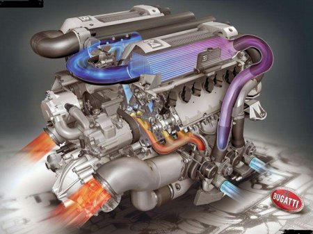

Reference. Modification of the Bugatti Veyron - Super Sport in the summer of 2010 set a world speed record of 431 km / h.
As the power of engines is constantly growing, developers are introducing new methods into the design of engine blocks. So if earlier the crankshaft was fixed in the bed of the block with covers on each main journal, then a technology was used that provides for a common cover for all crankshaft journals. This made it possible to increase the load on the engine and increase the rigidity of the block structure.
Also, to increase the rigidity and strength of the structure on certain models of blocks, the main covers of steel are also attached to the side through the body of the block, serving as a guarantee of a reliable connection.
The cylinder block (BC) is the main element of any reciprocating internal combustion engine. In this block, cylinder holes are made, inside which a mixture of fuel and air is burned. The result is the movement of the piston in the cylinder and the performance of useful mechanical work.

The cylinder block is the most great detail. Rest constituent elements engines, attachments and auxiliary mechanisms are mounted on the BC. These include the cylinder head, electric generator, air conditioner compressor, power steering, etc. A clutch for a manual or robotic transmission is attached to the cylinder block, as well as a torque converter housing for an automatic transmission.
Today, the upper part of the cylinder block is closed by the cylinder head (), and Bottom part The BC is covered by a sump of the lubrication system. Previously, there were lower-valve types of engines, when the elements installed today in the cylinder head (camshaft, valves and valve mechanism) were also in the cylinder block, and the cylinder head itself was a simple cover with holes for installing spark plugs.
The material for the manufacture of the cylinder block was gray alloyed cast iron or aluminum alloys. The finished BC is obtained by casting and subsequent machining. The cylinders in the cylinder block can be either part of the casting or act as separate bushings, which are called "sleeves". Said sleeves may be "wet" or "dry". This will directly depend on whether they have contact with coolant in the engine cooling channels.
The cast-iron cylinder block is noticeably stronger and more reliable, but has a large specific gravity. The aluminum block is significantly lighter, but requires special fortification load-bearing walls, block liners by installing special liners made of alloyed cast iron, coating cylinder walls with wear-resistant metals in a special galvanic way, etc.
The cylinder block performs a range of additional features, being the main part of the lubrication system and liquid cooling system for motors equipped with such systems. The fact is that in the BC there are special channels through which oil is supplied under pressure to the lubrication points, as well as channels of the cooling system through which the coolant (coolant) circulates inside the cylinder block through peculiar cavities. The channels for the circulation of the coolant form a "cooling jacket".
Similar articles
Removal of cracks in the cylinder block and cylinder head. Blocks and heads of engine blocks ... cylinder walls, as well as those surfaces where the BC and cylinder head fit.

The cylinder block is the basic part of the engine. In the cylinder block there are beds for crankshaft main bearings, camshaft bearings, as well as a cooling jacket surrounding the cylinders, the main oil line and places for attaching other components and devices. The V-shaped engine has two rows of cylinders in the block, located at an angle, and, accordingly, two block heads - for the right and left rows of cylinders.
The cylinder block of multi-cylinder engines is cast from gray cast iron or aluminum alloy as a whole part. As one piece with the cylinder block is cast and upper part engine crankcase.
The cylinder can be made directly in the block body or in the form of a replaceable sleeve made of acid-resistant cast iron and installed in the guide belts of the cylinder block. To reduce wear on the upper part of the sleeve, wear-resistant inserts are made in it.

Rice. 5. Cylinder block of the Moskvich-412 engine (a) and its bottom cover (b):
1 - pin for installing the ignition, 2 - cover of the transverse water channel with a gasket, 3 - bottom cover, 4.5 - right and left gaskets of the bottom cover, 6 - top cover of the gas distribution mechanism, 7 - place for installing the chain tensioner, 8 , 9 - right and left top cover gaskets, 10 - cylinder liner gasket, 11 - cylinder liner, 12 - water jacket hatch cover, 13 - hatch cover gasket; 14 - cylinder block; A - a tide for placing a water pump, B - a water distribution channel, C - a socket for a starter
Cylinder block for engines of cars "Moskvich" (Fig. 5) and GAZ-3102 it is cast from an aluminum alloy. Units and parts of the engine are attached to block 14 as to the base part during assembly. The cylinders of the block have replaceable cast-iron liners 11 inserted into the sockets of the block and pressed from above by the cylinder head. The outer walls of the sleeves are washed with coolant. In the lower part, each sleeve is sealed in the block with a gasket 10 made of red copper, sandwiched between the support ends of the sleeve and the block, and in the upper part - with a cylinder head gasket pressed by the plane of the head to the upper ends of all block liners. The cylinders are arranged in one row.
At the bottom of the block are five supports (main bearings) of the crankshaft. Cast iron main bearing caps are not interchangeable, each of them is based on two tubular pins through which the studs pass, securing the bearing caps to the block.
An aluminum clutch housing is attached to the rear end of the cylinder block. The correct position of the clutch housing on the block, ensuring the alignment of the crankshaft and the transmission input shaft, is achieved using two large diameter locating tubular pins pressed into the block. A water distribution channel B and a hatch of a cooling jacket are cast in the block, closed with a stamped cover 12 with a sealing gasket 13. On the same side there are channels of the engine lubrication system.
In the front left part of the block there is a tide A for accommodating the water pump, and in the rear left part there is a socket (window) B for the starter.
At the front ends of the block and cylinder head, two cast aluminum covers 3 and 6 are fixed, covering the timing chain drive. In the upper cover 6 of the timing gear, attached to the bottom cover 3 and to the front end of the cylinder head, a plunger with a spring is installed to tension the timing chain.
The cylinder block of the VAZ engine of the Zhiguli car is cast from special low-alloy cast iron. Cylinder liners are made directly in the block. To increase rigidity, the lower plane of the block is lowered 50 mm below the crankshaft axis. The main bearing caps are attached to the block with self-locking bolts.
The crankcase of the engine MeMZ-968 (Melitopol Motor Plant) of the car "Zaporozhets" of the tunnel type, is cast from a magnesium alloy. Solid side walls together with the front, rear and internal transverse baffles give the crankcase the necessary rigidity. In the upper part of the crankcase, four holes are bored, located in pairs at an angle of 90 °, into which the cylinders are installed. Cylinders and their heads are fastened with studs screwed into the crankcase.
The middle support of the crankshaft is detachable - from two halves, it is attached to the crankcase with two vertically located bolts. The front and rear main bearings of the crankshaft are one-piece. The rear one is pressed directly into the crankcase wall and is fixed with a stopper, the front one is pressed into the front support and fixed with a pin. The crankshaft main bearings are made of a special aluminum alloy. Above the bore for the main bearings in the front, middle and rear walls of the crankcase, the supports for the camshaft are bored out.
The cylinder head of the Moskvich-412, VAZ, ZMZ engines, cast from aluminum alloy, common to all cylinders, has a cooling jacket and is attached to the upper mating plane of the block. An iron-asbestos sealing gasket is placed between the cylinder head and the block. In the head are the combustion chambers of the cylinders and the gas distribution mechanism of the engine.

Rice. 6.
1 - tubular pin, 2 - head gasket, 3 - plug, 4 - sealing washer, 5 - cylinder head, 6 - stud, 7 - washer, 8 - nut, 9 - valve cover gasket, 10 - valve cover, 11 - oil filler plug, 12 - screw, 13 - plug plate, 14 - rear cover, 15 - rear cover gasket
On the left side of the cylinder head of the Moskvich-412 engine (Fig. 6), the outlet pipe of the cooling system, the fuel pump and the inlet pipeline are reinforced; with right side an exhaust pipeline is installed, above which spark plugs are placed in separate niches, screwed into the threaded holes of the combustion chambers.
On top of the head there is a cover 10 with an oil filler neck, which closes the valve mechanism of the engine. The connection of the cover with the head is sealed with a solid rubber cork gasket 9.

Rice. 7. Scheme of the engine of the GAZ-3102 car with pre-chamber torch ignition: 1 - prechamber feed channel, 2 - prechamber section of the carburetor, 3 - carburetor, 4 - inlet channel, 5 - inlet valve of the main chamber, 6 - rocker arm, 7 - rocker arm axis, 8 - prechamber valve, 9 - spark plug, 10 - prechamber , 11—prechamber nozzle, 12—main chamber, 13—rod, 14—pusher, 15—camshaft
In the engine of the GAZ-3102 car, the cylinder head provides a pre-chamber-flare method of igniting the working mixture (Fig. 7), due to which high combustion rates are achieved and efficient combustion lean mixtures. All this increases the efficiency of the engine and significantly reduces the toxicity of exhaust gases. The operating load range of this engine is fully provided by lean mixtures, and only to obtain maximum power(full or close to full opening of the throttle valves), the composition of the mixture is enriched with the prechamber-torch ignition method.
Next to the main combustion chamber is located additional camera 10 (pre-chamber) of small volume, connected to the main chamber by two holes 11 of small diameter - nozzles. The working mixture enters the prechamber through inlet valve 8 from the prechamber section of the carburetor. The mixture in the prechamber is ignited by candle 9, and the highly active combustion products of the rich prechamber mixture are ejected through two nozzles into the main combustion chamber in the form of torches, which ignite the lean working mixture located there. This achieves a reliable, fast and complete combustion lean working mixture in the main chamber.
The cylinder heads of the ZAZ-968 engine have air cooling fins with increased heat transfer, are cast from aluminum alloy, are interchangeable and common to two cylinders. Ceramic-metal bushings and valve seats made of special cast iron are pressed into the head. Bronze threaded bushings, fixed with pins, are wrapped in the holes for the candles.