DIY motion sensors. A simple do-it-yourself motion sensor - repair, installation
The presence of all kinds of detectors in the room allows you to control and manage most modern houses, remotely and automatically, according to a predetermined algorithm, without constant human control. In this article, we'll discuss how to do DIY motion sensor at home, and also consider the scope possible application device data.
A quick guide on how to make a motion sensor.
A limit switch or self-returning button installed at the door and responsive to opening and closing is the simplest motion sensor (penetration, opening). With the help of a simple circuit, this device turns on the light in the refrigerator. You can also equip a pantry or a vestibule of a hallway, a door in the entrance, a duty LED backlight using this switch or an alarm that will notify you of the operation.

Such devices, based on a reed switch and a magnet, can be seen on the doors and windows of protected objects. Lack of devices in a highly specialized application. They are not suitable for monitoring open areas, areas, passages.
For open passages, there are devices that respond to changes in environment. These include photo relays, capacitive (field sensors), thermal (PIR), sound relays. To fix the intersection of a certain section, control of an obstacle, the presence of movement of an object in the overlap zone, photo or sound echo devices are used.
The principle of operation of such devices is based on the formation of a pulse and its fixation after reflection from an object. When entering such a control zone, the characteristic of the reflected signal changes, and the detector generates a control signal at the output.
For clarity, a schematic diagram of the operation of a photorelay and a sound relay is presented:


interactive machines, automatic doors, voice detectors, burglar alarms and other automation that responds to the clear position of an obstacle or object.
It would be great to provide a motion detector with an illuminated mirror. The lighting will only turn on when a person is directly next to it.
Do-it-yourself motion sensor assembly diagram
Microwave sensor
To control open spaces and control the presence of objects in the controlled area, a capacitive relay has been developed. Operating principle this device is to measure the amount of absorption of radio waves. Everyone probably observed or was a participant in this effect, when approaching a working radio receiver, he begins to change the wave or and make noise, straying from the station. Let's talk about how to make a microwave-type motion sensor. The heart of this detector is a radio microwave generator and a special antenna.

On this circuit diagram presents a simple way to make a microwave motion sensor. Transistor VT1 is a high-frequency generator and part-time radio receiver. The detector diode rectifies the voltage by applying a bias to the base of the transistor VT2. The windings of the transformer T1 are tuned to different frequencies. In the initial state, when the antenna is not affected by external capacitance, the signal amplitudes are mutually compensated and there is no voltage on the VD1 detector. As the frequency changes, their amplitudes add up and are detected by the diode. Transistor VT2 starts to open. As a comparator, for a clear working out of the on and off state, a thyristor VS1 is used, which controls a 12 volt power relay.
Below is a working diagram of a presence relay on available components, which will help you assemble a motion sensor with your own hands or just come in handy to get acquainted with the device.

Thermal sensor
Thermal DD (PIR) is the most common sensor device in the business sector. This is due to cheap components, a simple assembly scheme, the absence of additional complex settings, and a wide temperature range of operation.

The finished device can be bought at any electrical store. Often this sensor is supplied with lamps, alarm devices and other controllers. However, now we will tell you how to make a thermal motion sensor at home. simple circuit to repeat looks like this:
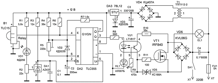
Special thermal sensor B1 and photo element VD1 are automated complex lighting control. The device starts working only after dusk, set by the level of the resistor R2, when a moving person enters the control zone. The time of the built-in timer can be set with the R5 regulator.
Homemade motion sensor on Arduino
An inexpensive sensor can be made from special boards for the radio designer on Aliexpress. From already ready-made modules a rather miniature device is assembled. For assembly, we need a motion sensor module for Arduino microcontrollers and a single-channel relay module.

Each board has a three-pin connector, VCC +5 volts, GND -5 volts, OUT output on the detector and IN input on the relay board. To make working device with your own hands, you need to apply 5 volts to the boards from the power source, and connect out and in together. The result should look like the diagram below.

The finished detector can be placed in the case or masked in a convenient place.
Now you know how to make a motion sensor with your own hands. We hope the provided diagrams helped you in assembling a homemade sensor!
This article is a continuation of the article about, which caused a heated discussion and many questions. Well, since there are a lot of questions about the repair of motion sensors, I decided to put them in a separate article-continuation.
The most important thing I want to convey is that the main thing is not to be able to solder and check the integrity of the elements. The main thing is to be able to think logically and critically, to explore, to analyze. And gain experience.
There are many motion sensor circuits, but the principle is the same. This principle and much more regarding this device is given at the link at the beginning of the article, once again I recommend studying it and comments on it. The same article provides links to other articles about motion sensors, you can download instructions and datasheets for details electrical circuit sensor.
Typical motion sensor malfunctions
The motion sensor for turning on the light may have the following faults:
- Does not turn on.
- Doesn't turn off.
- Turns on or off at the wrong time.
Below we will analyze these faults in detail.
More about diagrams
So, I will give the most popular motion sensor circuit once again:
This diagram was sent by my regular reader Alexander from the city of Korolev in December 2014, for which many thanks to him again. I will rely on this scheme in the text of the article, since it is the most typical. It should not be confusing that the circuit in our example will be scattered over two boards - low-current and power.
At the end of the article, the revision of this scheme will be given.
Now I am publishing a photo of the motion sensor boards, which were sent by my other reader - Renat.

Low current motion sensor board

Power board (power) motion sensor
Here is our correspondence with Renat:
Renat: Hello! According to the diagram and description, I have the same sensor, I don’t know the exact model, they asked me to look at “stopped working”. Stopped at the power board. I checked all the elements, after the diode bridge + 24V comes out, the zener diode gives out + 8V, soldered the second part of the circuit (the board where the IR receiver, microcircuit, etc.). And now, I can not understand why the relay is activated when I apply voltage?
Me: Is there an integral stabilizer (KREN) of type 7808, at the output 8V?
You need to connect everything, and then check.
When nothing is applied to the input of the key transistor, it can behave unpredictably.
Check the power transistor, relay, adjusting elements, soldering.
Climb deeper - you need to deal with the circuit - opamps, sensors, etc.
Renat: Hello Alexander! The integral stabilizer is not worth it. I connected it, everything is the same (the relay is triggered, it does not respond to the sensor, nothing changes from adjusting the sensor, time and the “day” / “night” mode.
Renat did a great job with his own hands, and I will try to help him in this article.
Where to start repairs if the sensor does not work
These my reasoning and techniques apply not only to a specific motion sensor, but also to many electronic devices. For example, to, the scheme of which is much simpler, but the principle is the same.
1. Check the correct connection. At this stage, it is also necessary to find out, after which the motion sensor does not work, under what circumstances. Options (brainstorming):
And what's fresh in the VK group SamElectric.ru ?
Subscribe and read the article further:
- light jump,
- turned off the electricity
- construction work,
- an electrician came to the neighbors,
- some kind of smell
- children twisted,
- hit,
- bitten dog,
- neighbors flooded,
- Yesterday there was a wind
- sometimes didn't work well
- etc.
At this stage, it is already possible to identify the direction in which to move on.
It is necessary to check the correct connection, make sure that the sensor receives proper nutrition, and if there are indicators, they should be lit. Some. Sometimes. Next, simulate the situation in which it should work.
2. Correct adjustments. It is possible that the regulators are not set correctly, and it is enough to set the sensor correctly. To do this, you need to put the regulators in the positions in which it is most likely to turn on: Set the illumination level to the position at which the sensor will work both day and night. Set sensitivity to maximum. Set the operating time to a minimum. In any case, it is worth turning the controls and analyzing how the sensor behaves, and whether it reacts at all.
We open the sensor
If after the first stage the sensor did not work, you need to take on the real work.
We open the sensor, look at the boards. The first thing to pay attention to is the integrity of the elements. Besides, knowing person the smell will say a lot. There should be no suspicious details - darkened, cracked, swollen, loose.
Tracks printed circuit board must be whole. Sometimes it happens that they crack, break near the places of rations (pyatakov). And of course, if the track is burned out, you need to restore it with a jumper, and analyze the cause.
We carefully check the soldering. In case of the slightest suspicion, we shake suspicious details, and solder these places. Often there are lead-in wires and wires between the boards, as well as adjusting elements (variable resistors).
Test run
Connect power to the sensor. As a load to indicate the operation of the sensor, I recommend using an incandescent light bulb with a power of 25-60 W. Otherwise, if you focus on the clicking of the relay, you may not hear or understand whether it is on or off. Infection check the relay and connections.
A better option is to connect through a transformer (with an output voltage of 220V) or a difavtomat, this will significantly reduce the risk of electric shock (we will work with open live parts!).
Another option is through a 60-100W incandescent bulb, this will save you from a short circuit. But it's not convenient.
On the use of circuit breakers.
We check the presence of the required supply voltage on the power board.
I won't tell you how to use measuring instruments, and how to check details. If you have questions, write in the comments.
In addition, I urge you to be careful and remember your safety! When repairing, it can be fucked up!
Once again, we return to where we started the repair (point 1). It is highly likely that after inspection, soldering, replacing visually faulty parts, everything will work.
Checking the food
In the motion sensor, the 220V input power is converted into the DC voltage required to power the circuit. As a rule, these are voltages of 8, 12, 15, 24 V different combinations, depending on the schema.
All voltages are measured relative to zero. The point where you can take zero - for example, minus the electrolytic capacitor at the output of the diode bridge.
In this case, you first need to check the voltage + 24V (see the diagram at the beginning of the article). If it is not there, it is necessary to check the restrictive (extinguishing) elements in front of the diode bridge, and the diodes themselves.
It is possible that the subsequent circuit “extinguishes”, or adds power. To verify this, you must disconnect the subsequent circuit from the power circuit.
We also check the low voltage + 8V, which is used to power the circuits of operational amplifiers.
If it is not there, we check the circuits before it (presence of + 24V), the stabilization circuits (zener diode), test disconnect the load.
Power circuits
We don’t go into the subtleties of operational amplifiers yet, we continue to explore the most obvious and probable.
In this case, this is a test of the operation of the power board relay. This relay turns on, that is, 24V voltage is applied to its coil if the key transistor opens. In this case S9013, n-p-n.
The test is best done with the low-current board completely turned off. Just, we turned it off when checking the power in step 4.
To check the operation of the transistor, it is necessary to close its base with the emitter, preferably through a resistor. It is there (R21, 20 kOhm), or use your own, about 2 kOhm - 33 kOhm. The transistor in this case will be closed (no current flows through it), and the relay should be turned off.
Next, we check the opening of the transistor and, accordingly, the inclusion of the relay. To do this, through the same resistor (a resistor is required, the jumper will burn the transistor) we connect the base of the transistor to + 24V. The relay should turn on.
If the transistor does not work, it must be checked with an ohmmeter by turning off the power (you can check it before manipulating the resistor). How to check a transistor - is it possible, I won’t write?
It is also possible that the relay is bad.
Subtleties
If the repair approached this stage without bringing results, then the repair can be considered complex and protracted. Like this article.
Therefore, I will not go into further subtleties, and if necessary, ask questions in the comments, I will definitely answer.
And yes, it would be better if, along with questions, you describe the progress of the repair according to the points of the article. And it will be generally great if there is a photo of the sensor, its boards and a circuit diagram.
Bonus. Reader question on sensor on LP8072C
Consider a motion sensor circuit on a specialized microcircuit LP8072C, which was sent by the reader Andrey (see the comment to the article dated 12/15/2015)

Sensor circuit on LP8072C
Once again I repeat his question, and answer:
Pulled out the sensor. Two blocks (power supply from the relay and all sensors on the other), with 3 wires - 0.5v, 11 pins per base.
Yes, the circuit is divided into two boards, as in the sensor at the beginning of the article. 0V - GND, on pin 5 of the microcircuit, 5V - power, VDD, on pin 13, and the output is controlled by a transistor.
Looked
13 - VDD 5v.
9 - CDS (photo diode circuit) from a variable resistor varies from 0.4 V to 2 V.
11 - there is 5v constantly - the relay has worked and the lamp is on, it does not depend on CDS.
Everything is correct so far. For interest, you can short-circuit the base and emitter of the transistor (for example, with a screwdriver, while the output 5V will drop on the 5.6kΩ resistor, this is not scary). Relay and load should turn off. This will indicate that the transistor and power circuits are working.
True, I put it on the table, soldered the wires to 0, and in series to 13, 9, 11 for the voltmeter.
When I measured between 0 and 11 - the sensor worked. It was possible to change the duration of the lamp burning with a variable resistor.
Between pins 5 and 11? This is just a power output, the voltmeter should not affect it. It turns out that the voltmeter shunted the output of the microcircuit, as I recommended above with a shorted base-emitter with a screwdriver. This should not be, either the microcircuit is faulty (most likely), or the voltmeter.
But I tried the sensor with a conventional 60 watt lamp. He was delighted, he collected everything in a searchlight - and again it burns constantly.
The burn time may be too long.Your circuit has an amplifier and a comparator.
There are conclusions of two op-amps here. Maybe there is something to look at them.
I noticed in your RC circuit a chain near the red wire.
Yes, this chain to reduce the sparking of the relay contacts does not play a role in this case.
I recommend changing the chip. But first, study the case when a measurement was taken and the sensor worked. The fact is that the input resistance of the voltmeter during measurement affects the circuit, and it is better that it be larger. Typically, the input resistance is about a hundred kiloohms, but cheap models can have 20 ... 50 kOhm (depending on the measurement limit). Therefore, take a resistor of about 100 kOhm, or a little less, and connect it in parallel with the output of the microcircuit. Or between the base and emitter of the transistor.
Such a resistor must be built inside the microcircuit, or it is placed between the base and emitter of the transistor, to increase the reliability of operation. As in the light sensor circuit.
And the microcircuit is most likely faulty (partially), or has exited the mode due to external strapping.
Let me know in the comments how the renovation goes.
Photo of the searchlight and motion sensor, Andrey sent:


Another addition
On February 10, my reader Mikhail sent a photo of the sensor (see comment for this date), in which the resistor on the board burned out when turned on:

If someone has such a sensor or its circuit, help Mikhail, tell the value of the resistor. Thank you in advance!
I will add that the resistor just does not burn, this is a consequence! 90% that after replacement it will burn out again!
Another bonus. Sensor repair video
Here is what my colleagues think about the repair of motion sensors:
By the way, do you know where the picture on the intro to the video is taken from? And what is missing from it? 😉 My logo!
More video:
Improved motion sensor circuit with corrected error
I am posting a revision of the scheme outlined at the beginning of the article. Her (revision) was sent by Aleksey Filippov from Lviv:

This is the gist of the upgrade.
Usage example: A spotlight on the porch of a house. How it works - the light in the hallway is on - the light from the street is constantly on, the light in the hallway is off - the spotlight on the street turns on from the motion sensor ( regular mode). There is no need for a separate switch (and wiring) and at the same time the light in the hallway does not turn on when the sensor on the street is triggered, that is, the circuits are decoupled.
I made this revision at work, assembled in two copies, one at the service, the other at the warehouse.
At the entrance to the service, it gets dark early in winter, the light in the room is on and the entrance is illuminated from the street for customers until work time, in the rest of the dark time, the spotlight with the sensor works as it should - in the normal mode.
Thanks Alexey!
Another motion sensor circuit
Photo of the motion sensor board for repair
Instead of smd resistor 100 ohm 1w (designation 101). I put the Soviet 2-watt on remote wires.

Replacing the resistor when repairing the motion sensor
Thank you all for your attention, if you have questions and comments - welcome to the comments!
This article is not a guide on how to install the sensor, but rather how to upgrade it yourself for home use. Now motion sensors are sold absolutely ready for installation. In addition to the motion sensor itself, it has a built-in light sensor and a timer. "So what should be modernized in it, if it already has everything?" - you ask? This will be discussed in this article. . .
This article is not a guide on how to install the sensor, but rather how to upgrade it yourself for home use. Now motion sensors are sold absolutely ready for installation. In addition to the motion sensor itself, it has a built-in light sensor and a timer. "So what should be modernized in it, if it already has everything?" - you ask? One of these upgrades we will have is a change in the power supply of the device itself.
In most cases, these devices use a power supply direct conversion. See drawing.


The efficiency of such a unit is negligible! The consumption of electricity by this unit will affect the homeowner's pocket quite significantly. As a result, it turns out that the sensor does not help to save, but on the contrary - it helps to spend!
What to do? - I suggest replacing this power supply with a transformer or switching one. They have a much higher efficiency. And if you choose specifically between pulse and transformer, then the efficiency is greater for a pulse power supply. Despite this fact, I still preferred a transformer one, besides, I had to introduce only a transformer into the device, since there is already a rectifier bridge and a stabilizer there. See drawing.


I decided to put a lamp with my upgraded sensor in the kitchen, so that when a person came up to the table or when he just entered (it all depends on how you need to configure the sensor), the light would turn on.
All installed, attached. See photo:

Next comes the most enjoyable part of all the work - these are tests. But here's the problem: the sensor refused to turn off the lamp! That is, it went out for a second and then turned on. What is the problem here, I thought? And I realized that when the contacts are opened in the sensor, a powerful electromagnetic impulse occurs, since there is a choke in my incandescent lamp, and the interference created by breaking the circuit interferes with the operation of the sensor and turns on the lamp again after turning it off. No matter what I do, no matter what the hindrance - quenching chains I would not put - nothing worked out for me. . .
All the same, a solution was found when I found a launch board from a burned-out economy lamp. By the principle of launch, it works in the same way as ordinary lamp daylight. That is, I can replace this heavy throttle, starter with this small board. Then I realized that I can kill two birds with one stone. Firstly, I will get rid of unnecessary interference, and secondly, I will save electricity. Indeed, compared to throttle system, the starting system for economy lamps is pulsed. This is how she saves money.
Everything. I ripped out all the insides and replaced them with this little board.


Now I have a kind of hybrid of an economy lamp with a fluorescent lamp.
I want to say that the Chinese again exaggerated. Instead of the prescribed 26 watts (as it was written on the body of the energy-saving lamp), it gave out about 17-19 watts. And so the glow became a little worse than with the throttle.
Along with this, there are several advantages. The first of these is savings, and the second is a quick and smooth start. That is, now the lamp ignites instantly like an incandescent lamp without blinking and without crackling the starter contacts.
Now all the work is completed, we proceed to re-testing. Everything works stably. At the bottom of the sensor are two variable resistors. One regulates the sensitivity of the light sensor, and the second regulates the burning time of the lamp, that is, the delay time of the motion sensor.
I attached the sensor to the bottom of the lamp. See photo.

Thus, he acted not entirely wisely. The light from the switched on lamp is reflected from the objects and hits the light sensor and the lamp starts blinking. The light sensor had to be abandoned. I lowered its sensitivity with a variable resistor to zero and the light sensor stopped working. Actually, the thing is necessary, but reinstalling the entire sensor in another place was not entirely practical. Now our device only responds to movement.

Basically, I'm happy. I set the lamp so that when you approach the table, it lights up, and when you leave, it turns off after 15 seconds. This time is necessary so that there are no sudden shutdowns when the sensor "gets used" to your presence at the table.
In conclusion, I want to remind you about security measures. If you are going to do something similar. All parts are under life-threatening voltage of 220 volts. During operation, make sure that the device is de-energized, in no case do not touch live parts when they are energized! After turning off, you must wait 15 minutes and only then start working, otherwise the high-voltage capacitors in the circuit will not have time to discharge and you may be electrocuted.
Be especially attentive and careful!
Or just make the light in the entrance of the house turn on only when someone is in it, you can make a motion sensor. Despite the fact that it seems complicated, within the framework of the article you can see for yourself: it is not. You may want to make a motion sensor for lighting. You can also implement burglar alarm- everything depends on your imagination.
Let's say a word about sensors
At first, the easiest and most primitive schemes will go, and in the end you will see much more complicated and more interesting solutions. But first, a little preface. If you have a desire to get acquainted with how infrared sensors work, or you think you will see circuits here that would be difficult to assemble at home, we will disappoint you. This article is completely and entirely aimed exclusively at those who are expanding their horizons, want to understand the principle of operation and assemble a few simple circuits in order to get a hand in creating such devices and understand how to make a motion sensor with their own hands.
The easiest and ... non-working option
So, the simplest option that radio amateurs could think of is to create a motion sensor that will be built on a wire resistor (also known as a potentiometric resistive converter). For greater accuracy, it should be clarified that this sensor is focused not so much on movement as on movement. But due to its simplicity, it is worthy of attention. Let's say you want to detect how some small object moves linearly from one point to another. For this, a displacement sensor will also come down. Here is its main purpose, which is well illustrated in the image. As you have already seen - nothing complicated. Some object is connected to the engine, and it, in turn, moves through the resistor. At the same time, the voltage of the voltmeter changes. But the design, alas, is not quite working. Its problem is that linear movement is not converted into voltages without flaws due to the fact that the sensors are connected to some kind of load (in this case it is a voltmeter).
Easiest working option

This do-it-yourself motion sensor can already be used to achieve motion control goals. But the price of this was a certain complexity of the provided scheme. Well, we suggest paying attention to the scheme, very carefully familiarize yourself with its device, and then study what is needed:
- GB1 - this is how the power source is designated;
- V - a voltmeter is connected here;
- R1 is a wire resistor, which is the most important such device in the circuit;
- R2 is a resistor that is needed to bypass the upper arm of the potentiometer.
- R3 - load resistance. You can connect any type of indication, from conventional light bulbs to circuits that reproduce sound.
Now look at the graph and remember the resistor from point #4. The lines represent the transformation of an object's motion into tension. Red - in cases where there is no R2, and green - if it is. About the advantages, we can say that it is easy to assemble, and it is quite accurate. There is only one drawback - it requires a little debugging before using the device.
Motion sensor with photocell

Here you have a more difficult one, and at the same time interesting job. First you need to get a photocell (a phototransistor is best). It can be made with your own hands due to the simplicity of the design or bought in a store. As part of the article, we will talk about MP41. To start, saw off at his body upper part to open the crystal. When light hits it, it will work as a photocell, albeit with a relatively low sensitivity. But, nevertheless, this is a full-fledged motion sensor, assembled with your own hands.
Scheme

In order for a sensor with a photocell to fully work, it is necessary to assemble a photodetector circuit. To influence the switch / switch, a photo relay is added - and the design is ready. As you can see, a do-it-yourself motion sensor is easy to make. In addition, experience and practice will allow you to gain experience and in the future to assemble devices that can be very useful at home, with the prospect of their successful commercial implementation.
Today, almost everyone knows what it is. This device has proven itself well, both in offices and in the private sector. The cost is not always affordable. In this article, we will describe in detail how to do it yourself homemade sensor for lighting, according to a simple scheme.
Basic information about the motion sensor
Consider some information about the motion sensor for lighting and its scope.
A motion sensor is a device whose main function is to recognize movement in its area of action. There are three types of sensor - passive, active and mixed.
The principle of operation of the active sensor is based on the radiation of ultrasonic and electromagnetic waves. Passive, has an infrared sensor that recognizes the heat of a person. Mixed motion sensors have both control devices.
The principle of operation of the device
Active sensors, by registering and comparing the data obtained during the radiation, notify of movement if a shift has occurred in the data.
Advantages of ultrasonic sensors:
- Low cost.
- Unaffected by weather conditions.
- Recognize motion regardless of material.
Cons of ultrasonic devices:
- Range limitation
- They are designed for fairly sharp movements.
- Animals are sensitive to ultra frequencies.
Most often, such devices are used in security systems for a car.
Advantages of RF motion sensors:
- Their sizes are small.
- Long range models available.
- Very accurate.
Cons of radio frequency devices:
- Their cost is quite high.
- Due to the high threshold of sensitivity, there are false fixations of movement.
- The high power of the device can have a bad effect on the human or animal body when it is in the field of action for a long time.
They are used in security systems.
Passive devices have infrared sensors that monitor the temperature in their radius of action. When the temperature data changes, the device is triggered. It is this device that is used more often for lighting in a residential area.
IR sensor device
Advantages of the infrared sensor
- They are safe for people and animals.
- They can be easily customized.
- They work great both indoors and outdoors.
- The price is satisfactory.
Cons of infrared sensor
- Such a device works only within certain temperature limits.
- It does not pick up objects covered with infrared shielding material.
- The device malfunctions with heat flows from heaters and warm wind.
Everything you need to make
Necessary tools and elements for assembly:
- Voltmeter
- soldering iron
- wires
- Plumbing gasket
- Screw
- Laser pointer
- transistors
- Photodiode FD 265
- Relay RES 55A
- Resistors
- Power Supply

Assembly diagram
Assembly works, work in stages
The motion sensor circuit for lighting is very simple. For those who have been involved in the repair of electrical appliances, it will not be difficult to do it.
Stages of work:
- To get started, prepare the power supply. The connector should be cut off. Then use a voltmeter to find positive.
- Then solder a 10 kΩ resistor.
- The photodiode with the cathode must be soldered to the resistor, which is soldered to the plus.
- By soldering, we attach a photodiode to the construction resistor with an anode. Solder the emitter of the transistor to the minus of the resistor. With the base VT 1, which, soldered to R1, connect the desired collector.
- Then you should connect the VT 2 emitter with a minus, the relay contact must be connected to the VT 2 collector. Another relay contact must be soldered to the plus of the power supply.
- The most common is the use laser pointer, we use it. To save money, we solder two more additional wires to the same power supply.
- We insert the cord into the water gasket all this, with the cap inside you need to insert it into the pointer - so that the cap rests against the spring inside.
- One wire from the power should be connected to the screw, and the other should be inserted between the gasket and the body of the pointer.
Before switching on, you should once again check the diagram. If everything agrees with the circuit, then we check the operation of the device.
How to connect the device and adjust the sensitivity
In order for the device to work properly and cope with the task, you need to responsibly treat its installation. The best place for installation is a doorway. For a more aesthetic appearance, the device can be placed in a plastic box by making a hole for the photodiode.
Mounts the sensor at a height of about a meter from the floor. The pointer should be installed parallel to the floor and so that the beam hits the photodiode, then the sensitivity during operation of the device will not be violated, it will not be necessary to resort to its repair.
At the end of the installation, you can hide the wires, so they will not spoil appearance and get under your feet. It is advisable to think about installing the device during repairs in the room, then it will be easier to hide the wires connecting to the lighting. When repairing, it is easier to think over the location of the device.
In order for the sensitivity to be good, you need to ensure that the pointer is set correctly. If it is installed correctly, then the sensitivity will be normal, and the device will not malfunction and will not need to be repaired.
When installing, remember that if the photodiode is dirty or the pointer beam is obstructed, it may disrupt the device's performance.
Summarize
Such a device is widely used in the installation security system using not only light, but also sound. This device lay down to connect to the lighting and make the light turn on automatically in the living room.
Thus, a system is created smart House. Enough economical option is such a device. It will help you significantly reduce your energy costs.

Various connection schemes
Very often it is used in bathrooms, in the kitchen, in hallways, and in the basements of a private house. In the bathroom and toilet, the device is connected not only to lighting, but also to ventilation, which greatly simplifies the ventilation of the room.