Ventilation in a private house - natural or forced? Natural and mechanical ventilation of residential premises Causes of disruption of natural ventilation.
Regular ventilation of residential and public buildings ensures the timely removal of excess heat, moisture and harmful gaseous impurities that accumulate in the air as a result of people and various household processes.
The air of poorly ventilated dwellings and other enclosed spaces, due to changes in the chemical and bacterial composition, physical and other properties, can have a harmful effect on health, causing or worsening the course of diseases of the lungs, heart, kidneys, etc. It has been established that prolonged inhalation of such air in combination with unfavorable temperature-humidity and air-ion conditions significantly affects the nervous system and general well-being of a person (headache, loss of appetite, decreased performance, etc.). All this indicates the great hygienic importance of ventilation of residential premises, since clean air, according to F.F. Erisman, one of the first aesthetic needs of the human body.
The amount of necessary exchange of indoor air with outdoor air depends on the number of people in the room, its cubic capacity and the nature of the work being done. It can be determined on the basis of various indicators, and as one of them, common in sanitary practice when examining residential premises, the content of carbon dioxide is taken. Ventilation should not allow the excess of carbon dioxide in the room above 1% o, which is accepted as an acceptable concentration for ordinary residential premises, classrooms, hospital wards, etc.
The cleanliness of the air in the premises is determined by the provision for each person of the necessary volume of air - the so-called air cube - and its regular replacement with outside air. The amount of ventilation air required for this per person per hour is called ventilation volume.
In residential premises, the norm of the air cube is 25-27 m3, the volume of ventilation is 37.7 m3, therefore, in order to completely remove the spoiled air and replace it with clean atmospheric air, it is necessary to ensure approximately 1.5-2-fold exchange of indoor air with outdoor air during I h. Thus, the frequency of air exchange is the main criterion for the intensity of ventilation. It is calculated by dividing the amount of air entering the room for 1 hour by its cubic capacity.
In rooms where hard physical work is done, for example, in sports halls, the indicated size of the air cube and ventilation volume will be insufficient and the air exchange rate will increase, however, within the permissible values that do not cause strong air currents. In children's institutions, the volume of ventilation may be less. It is also differentiated depending on the purpose of individual public buildings (hospitals, schools, etc.).
When rationing the volume of ventilation, sometimes instead of the frequency of air exchange, the amount of supply or exhaust air is indicated per person per hour.
Natural ventilation is the infiltration of outside air through various cracks and leaks in windows, doors, and partly through the pores of building materials in rooms, as well as their ventilation through open windows, vents and other openings arranged to enhance natural air exchange.
In both cases, air exchange occurs due to the difference in temperature between outdoor and indoor air and wind pressure. This exchange is most intense in an open building system, when the buildings are distant from each other and all four of their sides participate in the air exchange, and the rooms are located on two opposite facades, which creates through ventilation.
Air exchange due to infiltration provides only 0.5-0.75-fold air exchange for 1 hour. Since this is not enough, vents and transoms are used that fold at an angle of 45 ° into the room (Fig. 4.5). In this case, cold air enters the room first up, under the ceiling, and then, partially heated, goes down without forming sharp currents and without causing strong cooling of people. Form size
Rice. 4.5. Transom, a - intake of outside air; b - the flow of air into the room.
dots should be at least 1/50 of the floor area. In the cold season, ventilation is more effective with windows that are fully and often opened for 5-10 minutes than with windows that are slightly open for a long time. You should not be afraid of a short-term decrease in the temperature in the room, since the walls and furnishings cool slightly during this time and after the ventilation is completed, the air temperature will quickly recover, the main thing is that in this case a more complete change of air will occur.
In multi-storey buildings, to enhance natural ventilation, exhaust ducts are arranged in the internal walls, in the upper part of which there are intake openings. The channels lead to the attic into the exhaust shaft, from which air enters. This ventilation system works on natural draft due to the pressure difference formed in the ducts due to the temperature difference, which causes the warmer room air to move upwards. In the cold season, a natural draft exhaust system can provide 1.5-2-fold air exchange per hour; in warm season, its efficiency is insignificant due to the small difference in temperature between indoor and outdoor air.
Artificial ventilation. In public buildings designed to accommodate a large number of people, in hospitals, schools, and in production, natural ventilation alone is not enough to ensure the proper sanitary condition of the air. In addition, in hospitals and children's institutions during the cold season, it is not always possible to widely use it due to the danger of the formation of cold air currents. In this regard, mechanical ventilation is arranged, which does not depend on the outside temperature and wind pressure and provides, under certain conditions, heating, cooling and cleaning of the outside air. Ventilation can be local - for one room and central - for the entire building.
For local ventilation, supply or exhaust electric fans are used, which are installed in windows or wall openings. In public buildings, they are designed mainly for short-term action. In classrooms, gyms, fans operate during breaks between classes, and in a number of rooms with polluted air - periodically. In production, they function for a longer time. Most often, local exhaust ventilation is used, which removes spoiled air, and the influx of clean air is carried out by entering through windows and vents. In rooms with high air pollution (kitchens, toilets), only exhaust fans are installed.
However, local ventilation has certain disadvantages. When using the supply system in winter, cold air currents are formed in the room, the operation of the fan

Rice. 4.6. Scheme of the supply of o-exhaust artificial central ventilation.
the moat is often accompanied by significant noise, they spoil the appearance of the premises. The most modern type of local ventilation are air conditioning units.
Central ventilation is designed for air exchange in the entire building or in its main premises, it operates constantly or for most of the day. Depending on the purpose of the premises, central ventilation can be supply, exhaust or supply and exhaust, combining the supply of clean air with the removal of spoiled.
On fig. 4.6 shows a diagram of the supply and exhaust ventilation. Outside clean air, for example from a garden, is taken with the help of fans, sometimes at a considerable distance from the building, and is directed through the channel to the supply chamber, where it is cleaned of dust, passing through fabric or other filters. In the cold season, the air is heated to 12-14 ° C, in some cases it is humidified and supplied to the premises through channels in the inner walls. The supply ducts end with openings in the upper part of the walls to exclude the direct effect of colder air currents on people, and are covered with gratings. To remove spoiled air, another exhaust network of channels is laid, the openings of which are located in the lower part of the opposite inner wall; the channels lead to the attic into a common collector, from which air is removed to the outside using a fan.
The supply and exhaust ventilation system ensures the predominance of air inflow over the exhaust, which is especially important in operating rooms of hospitals. In showers, toilets, kitchens, as already mentioned, only an exhaust hood is arranged. In order to save money, many buildings also arrange only exhaust ventilation with the expectation that clean air enters through the vents,
From a hygienic point of view, a supply and exhaust ventilation system is more preferable, which provides an influx of clean heated and, if necessary, humidified air, which makes it possible to better maintain a normal temperature and humidity regime in the premises.
At present, a new, more advanced ventilation system has been developed - air conditioning, which allows you to automatically maintain optimal conditions for temperature, humidity, movement and air purity for the required time. For this, central air conditioning units are used, designed to service public buildings (hospitals, schools, etc.), railway cars, and room air conditioners for individual small-sized premises.
On fig. 4.7 is a diagram of an air conditioning unit. The outside air entering the air conditioners is heated or cooled to the required temperature, humidified

Rice. 4.7. Scheme of installation for air conditioning.
I - hole for suction of outside air; 2 - a hole for air to enter the room; 3 - filter; 4 - nozzles; 5 - a pipe supplying air to the nozzles; 6 - pipeline for supplying fresh chilled or heated water to the system; 7 - pump; 8 - electric motor; 9 - humidification chambers.
Organized natural ventilation in a residential building is an air exchange that occurs due to the difference in air density inside the building and outside, through specially arranged exhaust and supply openings.
For ventilation of premises in a residential building, a natural ventilation system is provided. Let's see how it works and how it works.
Natural ventilation device
Each entrance from the first floor to the last has a common ventilation duct that runs vertically from the bottom, up with access either to the attic or directly to the roof (depending on the project). Satellite channels are connected to the main ventilation duct, the beginning of which is located, as a rule, in the bathroom, kitchen and toilet.
Through these satellite channels, the "exhaust" air leaves the apartments, enters the common ventilation shaft, passes through it and is discharged into the atmosphere.
It seems that everything is extremely simple and such a mechanism should work flawlessly. But there are many things that can interfere with the normal operation of ventilation.
The most important thing in the work of natural ventilation is that air must be supplied to the apartment in sufficient quantities. According to the projects, according to SNiP, this air should enter through the "leaks" of window openings, as well as by opening the vents.
Extract from SNiP 2.08.01-89 (minimum air exchange parameters for an apartment).
But we all understand that modern windows in the closed state do not let in any sounds, let alone air. It turns out that you need to keep the windows open all the time, which of course is not possible for a number of reasons.
Causes of disruption of natural ventilation
- Re-equipment of ventilation channels
- Debris in the ventilation duct
- Incorrect connection of exhaust hoods
- seasonality
It happens that the ventilation stops working due to active neighbors who could simply break the ventilation duct to expand the living space. In this case, for all residents whose apartments are located below, the ventilation will stop working.
It often happens that something gets into the ventilation shaft and simply does not allow air to move freely. If this happens, then you need to contact the appropriate structure, it is forbidden to climb into the ventilation duct on your own.
Also a common problem is the connection of kitchen hoods (exhaust hoods) of high power to the satellite channel, which is not intended for this. And when such a hood is turned on, an air lock forms in the common ventilation duct, which disrupts the operation of the entire system.
Unfortunately, the operation of the natural ventilation system is also influenced by the temperature regime, in the cold season it works better, and in the summer, when the temperature rises outside, it works less. To this, several negative points described above are added, and the operation of the entire system comes to naught.
And of course, there are mistakes during construction made by the contractor for one reason or another ... Only the installation of supply and exhaust ventilation equipment will help here.
Natural ventilation operates all year round 24 hours a day. Therefore, a round-the-clock supply of air to the room is necessary. If it is not there, then in winter, when the windows are closed, condensation may occur, an increase in humidity up to the formation of mold, to avoid this, install supply valves, this will improve ventilation in the room and get rid of excess moisture.
For the organization of good air exchange in the apartment all year round. A ventilator will be required. Thanks to this device, you do not have to open windows, and fresh and clean air will always enter the apartment.
Central Scientific Research
and Design and Experimental Institute
engineering equipment of cities, residential and public buildings
(TsNIIEP engineering equipment) State Committee for Architecture
Reference guide toSNiP
The series was founded in 1989
HEATING AND VENTILATION OF RESIDENTIAL BUILDINGS
MOSCOW
STROYIZDAT
Recommended to publication section heating, ventilation And conditioning air Scientific-technical advice TsNIIEP engineering equipment State Committee for Architecture
FOREWORD
The manual was developed in accordance with SNiP 2.08.01-89 Residential buildings. The parameters of the microclimate in the premises of residential buildings and the air-thermal regime established by SNiP are determined not only by the operation of heating and ventilation systems, but also by the architectural, planning and design solutions of these buildings, as well as the thermophysical characteristics of building envelopes. In addition to the above, in residential buildings a great influence on the microclimate is exerted by the peculiarities of the operation of apartments by residents. The combination of these factors determines the operating costs of heat and the level of air-thermal comfort. With this in mind, the organization and rational maintenance of the air-thermal regime in residential buildings is a complex task. However, the current system of regulatory documents, specialized in certain sections of the design, does not take into account this complexity.
The design of heating and ventilation systems is carried out in accordance with the requirements of SNiP 2.04.05-86. In this case, reference manuals to SNiP, reference books, advisory and other literature containing methods for thermal and hydraulic calculation of systems, instructions for their design, equipment characteristics are used. The listed documents, aimed at specialists in the field of designing heating and ventilation systems, do not cover the entire range of issues of ensuring a normalized air-thermal regime in residential buildings with a minimum consumption of thermal energy. Therefore, when compiling this Handbook, the main attention was paid to the issues that most often arise among designers and testify not only to the lack of clarity of individual provisions of the regulation, but also the lack in some cases of understanding the significance of various elements of residential buildings in their air-thermal regime.
The manual was developed by TsNIIEP of engineering equipment of the State Committee for Architecture (candidates of technical sciences A.Z. Ivyansky and I.B. Pavlinova).
1. DESIGN AND PLANNING SOLUTIONS FOR RESIDENTIAL BUILDINGS
1.1. The air-thermal regime in the premises is one of the main factors determining the level of comfort in residential buildings. The unsatisfactory microclimate makes them uninhabitable.
1.2. Optimization of the air-thermal regime of apartments requires their isolation from adjacent premises in order to minimize the amount of overflowing air.
The flow of air into apartments from adjacent apartments and (or) stairwells is one of the main reasons that reduce the efficiency of the ventilation system and lead to an unsatisfactory state of the air in apartments. With this in mind, the construction part of the project of a residential building should provide for planning, design and technological solutions that minimize the possibility of air flowing through the entrance doors to apartments, junctions of enclosing structures, passing engineering communications through them, etc.
1.3. As experience in the operation of modern residential buildings of mass development shows, one of the most common causes of underheating of premises with the calculated heat transfer of the heating system is the actual underestimation of the resistance to air penetration of window filling against the regulated SNiP II-3-79 ** for the window design provided for by the project. This underestimation takes place due to the poor quality of the manufacture of window blocks; poor-quality sealing of window blocks into the wall panel; absence of gaskets sealing the porches or their non-compliance with the design ones, etc.
To exclude underheating of residential buildings at low outdoor temperatures as a result of the above-mentioned factor, it is recommended to conduct selective full-scale tests of windows in order to determine their actual air permeability, characteristic of a particular building area, for example, according to the method of full-scale tests of air exchange of residential buildings of TsNIIEP engineering equipment.
1.4. The dimensions of the light openings determine not only the calculated heat loss of the premises, but also the thermal regime in them due to negative radiation and falling cold air flows in winter and overheating in summer. Therefore, one should strive for the minimum allowable dimensions of light openings from natural lighting conditions, but not more than with a ratio of their area to the floor area of the corresponding premises of 1:5.5.
1.5. When choosing a constructive solution for attics, preference should be given to sectional warm attics used as a static pressure chamber of a natural exhaust ventilation system. Open lofts with exhaust air venting require further research and design improvement, and are not currently recommended for use in mass housing construction. In buildings with a height of less than 5 floors, in which the construction of a warm attic is impractical, the exhaust ducts should go directly into the shafts leading above the roof level.
1.6. Zoning of apartments is associated with an increase in the number of utilities, which leads to an increase in material consumption and operating costs. The presence of exhaust ducts in different places of the apartment significantly reduces the reliability and efficiency of the natural exhaust ventilation system.
1.7. The adjoining of sanitary facilities and ventilation units to the outer walls of apartments makes it difficult to ensure a satisfactory humidity regime in sanitary facilities and requires special solutions to increase the temperature of their enclosures, which are subject to development and verification in mass construction.
1.8. Planning solutions for apartments in terms of organizing ventilation should mainly be aimed at excluding horizontal air ducts within the apartment; to ensure the direct supply of air from the kitchen, bathroom and toilet to the ventilation unit; for providing access to ventilation units during installation, as well as for revision and sealing of joints during operation.
1.9. In the basements and basement floors of apartment buildings and dormitories with heating systems connected to district heating networks, with an estimated heat loss of buildings during the heating period of 1000 GJ or more, a room should be provided for placing an individual heating unit (ITP).
The ITP room must have a height (in cleanliness) of at least 2.2 m, in places where service personnel can access it - at least 1.9 m; should be separated from other rooms, have an outward-opening door, lighting. The floor must be concrete or tiled with a slope of 0.005. A ladder should be installed in the floor of the ITP, and if gravity water drainage is not possible, a drainage pit with dimensions of 0.5 x 0.5 x 0.8 m, covered with a removable grate, should be installed. To pump water from the pit into the sewer system, a drainage pump should be installed.
The estimated heat loss of the building for the heating period is recommended to be determined in accordance with Sec. of this Guide.
1.10. The use of kitchen niches with mechanical exhaust ventilation is allowed only in residential buildings, all apartments of which are equipped with a mechanical exhaust.
1.11. The arrangement of loggias with floor exits from the staircase is associated with a significant additional heat consumption and is not recommended if this is not related to fire safety requirements.
1.12. In the course of a feasibility study of a constructive solution for an attic, in addition to traditional factors, one should also take into account the costs of insulating the utilities located in them and their operation.
2. CALCULATION OF HEAT LOSS
2.1. Estimated heat losses compensated by heating should be determined from the heat balance. The heat balance of a residential building as a whole and each heated room is found from the equation
Q tr + Q in + Q c.o + Q ins + Q life = 0, (1)
where Q tr - transmission heat losses through the fences of the building (premises); Q c - heat costs for heating outdoor air in the volume of infiltration or sanitary norms; Qс.о - thermal power of the heating system, which is the desired value when determining the heat balance; Q ins - heat input due to solar radiation; Q household - total heat gains from all internal sources of heat, with the exception of the heating system (household conventionally includes heat releases from household appliances and lighting fixtures, stoves, hot water piping and directly consumed hot water, people in the apartment).
2.2. Calculation of transmission heat losses through external enclosing structures is carried out according to adj. 8, SNiP 2.04.05-86. At the same time, the design air temperatures of the premises tcal are taken in accordance with SNiP 2.08.01-89 Residential buildings.
2.3. When calculating transmission heat losses through the internal fences of residential buildings, heat transfer should be taken into account:
a) through attic floors in houses with a warm attic;
b) through floors above unheated basements and undergrounds (including when placing heat pipes in them);
c) through the internal railings of the staircase (including smoke-free).
At the same time, the coefficient P are taken equal to 1.
The air temperature in basements (undergrounds) and warm attics should be determined from the heat balance of these rooms (when compiling the heat balance of a warm attic, Recommendations on the design of reinforced concrete roofs with a warm attic for multi-storey residential buildings / TsNIIEP dwellings, 1986) can be used).
After determining the air temperature according to paragraphs. but And b for given building structures, it is necessary to check compliance with the normalized value Dtn according to table. 2 SNiP II-3-79 ** Building heat engineering.
In the stairwells of houses with apartment heating, the calculated air temperature is not standardized.
2.4. The heat consumption for heating the outside air entering the premises is determined twice:
a) based on the amount of air infiltrated through leaks in the external enclosures;
b) based on the sanitary standard of ventilation air 3 m3/h per 1 m2 floor area of living rooms.
For living rooms, of the two values \u200b\u200btaken larger, for kitchens - according to p. but.
2.5. Heat consumption qi, W, for heating the infiltrating air is determined by the formula
qi= 0.28S Gikic(tp - ti), (2)
where Gi- the amount of infiltrating air, kg / h, through the enclosure of the room, determined by the formula (); from- specific heat capacity of air, equal to 1 KJ/(kg×°C); ki- coefficient for taking into account the influence of the oncoming heat flow in structures is taken according to adj. 9 to SNiP 2.04.05-86; tp, ti- calculated air temperatures, °C, indoors and outdoors during the cold season (parameters B).
Calculation of heat consumption for heating infiltrating air for all premises of residential buildings (including staircases, elevator lobbies, floor corridors), taking into account the generalized results of field tests of various elements of fencing for air permeability and the results of machine counting (in tabular form), can be carried out using materials TsNIIEP engineering equipment.
2.6. Heat consumption Q c, W, for heating the sanitary norms of ventilation air are determined by the formula
Q in = ( tp - ti) BUT n, (3)
where A n is the floor area of the dwelling, m2.
2.7. The amount of air infiltrated into the room S Gi, kg/h, should be determined by the formula*
* Interpretation of formula (3) adj. 9 SNiP 2.04.05-86 for residential buildings.
where A1, A2 are the areas of windows (balcony doors) and external doors, respectively, m2, l- length of joints of wall panels, m; R 1 and R 2 - resistance to air penetration, respectively, windows (m2×h (daPa) 2/3/kg) and doors (m2×h (daPa) 0.5/kg); determined according to SNiP II-3-79 ** (app. 10) and SNiP 2.04.05-86 (app. 9) or according to the results of field tests; Dp - calculated pressure difference on the outer and inner surfaces of the outer enclosures of the room, daPa; Dp1et - pressure difference Dp, determined for the premises of the 1st floor, daPa.
2.8. For residential buildings with natural exhaust ventilation, the calculated pressure difference DR find by formula*
2.11. Heat consumption, GJ, for the heating period S Q found from expression
![]() (7)
(7)
where Q- estimated heat consumption by the heated building (facade); tp- design temperature of internal air, °С; - average outdoor temperature for the heating period, °С, adopted according to SNiP 2.01.01-82; ti- calculated outdoor air temperature (parameters B), °С; P- the number of days of the heating season (the duration of the period with an average daily air temperature £ 8 ° C), taken according to SNiP 2.01.01-82.
With a reasonable degree of accuracy, one can take
(tp - )/(tR - ti) = 0,5.
Table 1
Q e - additional heat losses associated with the cooling of the coolant in the supply and return lines passing in unheated rooms, kW. the value Q e is recommended to be determined with an efficiency coefficient, isolation of 0.75, according to table. .
table 2
|
Heat transfer of 1 m of insulated pipe, W/m, nominal diameter, mm |
|||||||||||
|
* t d - temperature of the heat carrier at the inlet to the heating system (for supply pipelines) or at the outlet from it (for return pipelines), ° С; t c - air temperature of the premises in which the pipelines are laid, ° С; determined by the heat balance of these rooms (see section). |
|||||||||||
3.2. Estimated coolant flow in risers (branches) of the heating system G st, kg/h, should be determined by the formula
where Q st - total heat loss of premises served by a riser (branch) of the heating system, kW; from c - specific heat capacity of water, kJ/(kg×°С); D t- temperature difference of the coolant at the inlet and outlet of the riser (branch). When pre-calculating D t it is recommended to take 1 °C less than the calculated temperature difference of the coolant in the heating system.
3.3. heat flow Q heater is determined by the formula
 (10)
(10)
where Q n.p - rated heat flow of the heater, kW; P And R- exponents, respectively, at relative temperature difference and coolant flow rate; b3 - dimensionless coefficient taking into account the number of sections in the radiator (only for cast iron sectional radiators); b4 - dimensionless coefficient, taking into account the method of installation of the heater; b- dimensionless coefficient for the design atmospheric pressure; Wed- correction factor taking into account the connection scheme of the heater and the change in the exponent R in various ranges of water flow; y1 - coefficient taking into account the decrease in heat flow during the movement of the coolant according to the "bottom-up" scheme; M- water flow through the heater (for convectors - for each tube), kg / s; q- temperature difference, °C.
![]() , (11)
, (11)
where t n and t k is the temperature of the heat carrier at the inlet and outlet of the heater, °C; D t pr - temperature difference of the coolant at the inlet and outlet of the heating device, ° С; t c - design air temperature of the heated room, °C.
Values Q n.p., P, R, b3 , b, Wed, y1 should be taken according to the information releases of the institutes of the USSR Ministry of Construction Materials, reference books, catalogs, etc.
For the most popular heating appliances, the necessary information is contained in the following literature:
Method for determining the nominal heat flux of heating appliances with water as a coolant / Research Institute of Sanitary Engineering, 1984.
3.4. The ratio of equivalent square meters (ekm) and kilowatts is recommended to be taken:
for radiators and convectors without casing 1 ekm - 0.56 kW,
for convectors with casing 1 ekm - 0.57 kW.
The rated heat flow of heating devices in kW is determined at a difference in the average temperatures of the heat carrier and air of 70 ° C, the flow rate of the heat carrier through the device is 0.1 kg / s, and atmospheric pressure is 1013 GPa.
The actual heat flow from the heaters in the heating system, depending on the values of the listed factors, will differ from the nominal one up or down. As a result, there is no formal correspondence in kilowatts between the heat losses of the premises and the nominal heat flow of the heating devices installed in them (for example, a heating device with a nominal heat flow of 1.3 kW should be installed in a room with a heat loss of 1 kW), which is a defect of the new heating appliances meter, and not calculation errors.
3.5. Heating systems for residential buildings with a heat consumption for the heating period (see paragraph of this Manual) of 1000 GJ or more should be designed per front for the possibility of automatic separate control of each facade. If the heat consumption for the heating period is less than 1000 GJ (240 Gcal), automatic regulation of the heat flow is provided for in the justification.
3.6. Automatic regulation of heat consumption in heating systems should be designed in accordance with the “General Provisions for Equipping Metering Devices and Automatic Control of Gas Supply, Heating, Ventilation, Hot Water Supply, Heating Networks and Boiler Houses”, approved by the USSR Gosstroy.
Since 1989, the Moscow Plant of Thermal Automation of the USSR Ministry of Instrumentation has begun production of Teplar-110 microprocessor controllers designed to control two facade heating systems and a hot water supply system for residential buildings (with one device). "Tepler-110" is the most effective specialized regulator.
3.7. When automating heating systems, indoor air temperature sensors should be installed in the air flow in the center of the main ducts of ventilation units (with separate ventilation units - kitchen ones) 700 - 800 mm below the confluence of the satellite duct with the collection duct in the ventilation unit of the upper floor. In case of façade regulation, it is recommended to use the ventilation units of apartments for placing sensors, the premises of which are oriented mainly to one facade of the building. In houses with meridional orientation, it is recommended to install at least one sensor in the ventilation unit of the apartment adjacent to the northern end of the building. In other cases, one should strive for the minimum length of connecting lines of sensors with control devices.
3.8. For multi-storey residential buildings, the main heating solution is single-pipe water heating systems made of unified units and parts, with top or bottom filling and artificial circulation induction. For buildings up to 10 floors inclusive, one-pipe systems with P (T)-shaped risers can be used. The parameters of the heat carrier in water heating systems should be taken as 105 - 70 °С, if the indicated parameters are not provided with heat sources (individual or group boilers) - 95 - 70 °С.
As heating devices, cast-iron sectional radiators of the MS type and steel convectors of the Universal type are preferred, which provide regulation of the heat flow "by air" due to the air valve included in their design, which makes it possible not to install control valves in front of them.
3.9. Surface heating systems with heating elements in single-layer and three-layer external wall panels, compared to traditional central heating systems, are a progressive technical solution that, with high-quality performance, allows to increase the industrialization of installation work, reduce the cost of construction and reduce metal consumption with a high level of thermal comfort in serviced premises.
Along with this, it should be taken into account that a large amount of “hidden” work, characteristic of panel heating systems, imposes increased requirements on the culture of production and compliance with technological discipline. In emergency situations of a large scale, surface heating systems require more precise actions of the operating personnel. In this regard, decisions on the use of panel heating systems in specific cities (districts) are made by the state construction of the Union republics, regional (city) executive committees, taking into account the preparedness of house-building plants, heat supply and operating organizations.
When designing surface heating systems, the “Guidelines for the design and implementation of surface heating systems with steel heating elements in the outer walls of large-panel buildings” (SN 398-69) can be used with changes arising from the current regulatory documents.
3.10. In residential buildings connected to district heating networks with a design temperature of the coolant (water) of 150 °C at parameters B outside air and guaranteed differential pressure, a system with staged heat recovery (CRT) can be used to reduce the consumption of heating appliances.
The design of the SRT system is carried out in accordance with the "Standards for the design of heating systems with staged heat recovery" (RSN 308-85 Gosstroy of the Ukrainian SSR).
3.11. When designing heating systems for residential buildings being built in the Northern building-climatic zone, in the development of existing regulatory documents, it is additionally recommended:
a) design heating systems with local heating devices with dead-end wiring of main pipelines with the number of risers connected to one branch not more than 6. With a larger number of risers, as a rule, provide for the associated movement of the coolant;
b) for heating stairwells, provide:
high steel convectors in vestibules, including their heating system, installed on both pipes in places inaccessible for accidental closing of valves. The load of high convectors should be taken equal to the heat loss of the vestibule, taking into account the heat loss through the entrance doors;
steel convectors on the floors, connecting them to independent risers according to a single-pipe flow pattern. Lay risers of stairwells within 1 - 2 floors in apartments, elevator halls or other rooms heated by the main heating system of buildings. The design air temperature in the stairwells is taken to be 18 °C;
c) heating of waste collection chambers, as a rule, should be provided with coils made of smooth pipes connected to the heating system according to a flow scheme, with the installation of shut-off valves on both connections. The design air temperature in the waste collection chamber is to be 15 °C;
d) take unaccounted circulation pressure losses in the heating system equal to 25% of the maximum pressure losses;
e) when installing mixing pumps in heating systems, provide a backup pump;
f) in heating systems of residential buildings with a number of floors of 3 or more, on each riser, provide shut-off valves to turn them off and drain valves with a fitting for emptying;
g) lay risers at the intersection of floors using sleeves;
h) for risers and connections to heating appliances, use ordinary steel pipes in accordance with GOST 3262-75 *.
All of the above is aimed at improving the reliability of heating systems built in the Northern building-climatic zone and reflects the experience of field surveys.
4. VENTILATION
4.1. In mass housing construction, the following apartment ventilation scheme has been adopted: exhaust air is removed directly from the zone of its greatest pollution, i.e. from the kitchen and sanitary facilities, through natural exhaust duct ventilation. Its replacement occurs due to the outside air entering through the leaks of the external fences (mainly window filling) of all the premises of the apartment and heated by the heating system. Thus, air exchange is ensured in its entire volume.
In the case of family occupancy of apartments, to which modern housing construction is oriented, interior doors, as a rule, are open or have a trimming of the door leaf, which reduces their aerodynamic resistance in the closed position. So, for example, the gap under the doors of the bathroom and the restroom should be at least 0.02 m high.
The apartment is considered as a single air volume with the same pressure.
Rationing of air exchange is carried out on the basis of the minimum amount of outdoor air required for hygienic requirements per person (approximately 30 m3 / h) and is conditionally attributed to the floor area. The increase in the occupancy rate, as well as the increase in the height of the premises, is not associated with the indicated amount of air.
It is not recommended to remove air directly from rooms in multi-room apartments, since this violates the pattern of directional air movement in the apartment.
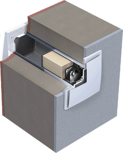
4.13. Increasing the operational reliability (prevention of "overturning" the air flow) of the natural exhaust ventilation system and at the same time reducing material consumption and labor costs are achieved by using one vertical exhaust duct per apartment by using combined ventilation units. An example of a solution for a combined ventilation unit combined with a sanitary cabin is shown in fig. .

Rice. 3. Combined ventilation unit combined with a sanitary cabin
1 - "cap" with a ventilation block; 2 - the bottom of the cabin; 3 - sealing gasket; 4 - wire guards 5 - intermediate floor
The use of two combined or combined and separate ventilation units in zoned apartments leads, as a rule, to excessive intensification of air exchange and is therefore undesirable.
When using two ventilation units in the same vertical of apartments, it is necessary to ensure the same conditions for the outflow of ventilation air into the atmosphere (in particular, the emission mark in the case of independent mines).
4.14. The use of identical ventilation units along the height of the building predetermines the uneven air removal along the vertical of the apartments.
Increasing the uniformity of distribution of air flow rates is achieved by increasing the resistance of the entrance to the ventilation unit or providing a variable value of the resistance to the entrance to the ventilation unit according to the height of the building. The latter can be done using ventilation grilles with mounting adjustment (for example, the design of TsNIIEP engineering equipment) or special linings (for example, from hardboard) with holes of different sizes at the entrance to the ventilation unit.
Expansion of the scope of ventilation units for buildings of various heights and a change in their nominal performance (see p. ) are possible with the help of specially designed overlays.
4.15. The design and technology of installation of ventilation units should provide for the possibility of sealing their interfloor joints.
The tightness of the ventilation network is of particular importance for natural exhaust ventilation. The presence of leaks leads not only to excessive air exchange in the apartments of the lower floors of multi-storey buildings, but also to the emissions of polluted air through them from the collection channel to the apartments of the upper floors. The projects must provide for a special technology for sealing interfloor joints of ventilation units using elastic gaskets.
4.16. Stable removal of air from apartments on the upper floors is ensured with the right choice of ventilation units for buildings of a specific number of storeys and attic design.
The installation of exhaust fans at the entrance to the ventilation unit of the two upper floors, provided for by SNiP, worsens the air exchange in the apartments, since the fans are not designed for continuous operation, and during periods of inactivity they make it difficult to remove air due to excessive resistance.
4.17. The structures of the transit sections of ventilation units passing through cold or open attics, as well as ventilation shafts on the roof, must have a thermal resistance not less than the thermal resistance of the outer walls of residential buildings in a given climatic region. To reduce the weight and dimensions of these structures, provided for in this paragraph, thermal resistance can be achieved through effective thermal insulation. The same applies to the ventilation sections of the sewer risers and the garbage chute.
Description:
The quality of the air we breathe depends on the efficiency of ventilation. Underestimation of the influence of air exchange on the state of the air environment in residential apartments leads to a significant deterioration in the well-being of the people living in them.
Natural ventilation of residential buildings
E. Kh. Kitaitseva, associate professors of Moscow State University of Civil Engineering
E. G. Malyavina, associate professors of Moscow State University of Civil Engineering
The quality of the air we breathe depends on the efficiency of ventilation. Underestimation of the influence of air exchange on the state of the air environment in residential apartments leads to a significant deterioration in the well-being of the people living in them.
SNiP 2.08.01-89 "Residential buildings" recommends the following air exchange scheme for apartments: outside air enters through the open windows of living rooms and is removed through exhaust grills installed in kitchens, bathrooms and toilets. The air exchange of the apartment must be at least one of two values: the total exhaust rate from the toilets, bathrooms and kitchen, which, depending on the type of stove, is 110 - 140 m 3 / h, or the inflow rate equal to 3 m 3 / h for each m 2 of living space. In standard apartments, as a rule, the first version of the norm turns out to be decisive, in individual apartments - the second. Since this version of the norm for large apartments leads to unreasonably high ventilation air consumption, the Moscow regional norms MGSN 3.01-96 "Residential buildings" provide for air exchange in living rooms with a flow rate of 30 m 3 / h per person. In most cases, design organizations interpret this standard as 30 m 3 / h per room. As a result, in large municipal (not elite) apartments, air exchange can be underestimated.
In residential buildings of mass development, natural exhaust ventilation is traditionally performed. At the beginning of mass housing construction, ventilation was used with individual ducts from each exhaust grille, which were connected to the exhaust shaft directly or through a collection duct in the attic. In buildings up to four floors, this scheme is still used today. In high houses, to save space, every four to five floors, several vertical channels were combined with one horizontal one, from which the air was then directed to the mine through one vertical channel.
At present, the principal solution for natural exhaust ventilation systems in multi-storey buildings is a scheme that includes a vertical collection channel - "trunk" - with side branches - "satellites". Air enters the side branch through an exhaust opening located in the kitchen, bathroom or toilet and, as a rule, in the interfloor ceiling above the next floor, is bypassed into the main collection channel. Such a scheme is much more compact than a system with individual channels, can be aerodynamically stable and meets the requirements of fire safety.
Each vertical of apartments can have two "trunks": one for transit of air from kitchens, the other from toilets and bathrooms. It is allowed to use one "stem" for ventilation of kitchens and sanitary cabins, provided that the place of connection of the side branches to the collection channel at one level must be at least 2 m above the level of the serviced premises. One or two last floors often have individual channels that are not connected with a common main "trunk". This happens if it is structurally impossible to connect the upper side channels to the main channel according to the general scheme.
In typical buildings, the main element of the natural ventilation system is a floor ventilation unit. In buildings built according to individual projects, exhaust air ducts are most often made in metal.
The ventilation unit includes a section of the main channel of one or more side branches, as well as an opening connecting the ventilation unit with the serviced premises. Now the side branches are connected to the main channel through 1 floor, while earlier solutions provided for connection through 2 - 3 and even 5 floors. The interfloor joint of ventilation units is one of the most unreliable places in the exhaust ventilation system. To seal it, cement mortar is sometimes used, laid in place along the upper end of the underlying block. When installing the next block, the solution is squeezed out and partially overlaps the cross section of the ventilation ducts, as a result of which their resistance characteristic changes. In addition, there were cases of leaky sealing of the joint between the blocks. All this leads not only to an undesirable redistribution of air flows, but also to the flow of air through the ventilation network from one apartment to another. The use of special sealants still leads to the desired result in terms of the complexity of the sealing operation with the inaccessibility of the seam.
In order to reduce heat loss through the ceiling of the upper floor and to increase the temperature on its inner surface, most typical projects of multi-storey buildings provide for the installation of a "warm attic" about 1.9 m high. Air enters it from several prefabricated vertical channels, which makes the attic a common horizontal area ventilation systems. Removal of air from the attic space is carried out through one exhaust shaft for each section of the house, the mouth of which, in accordance with SNiP "Residential Buildings", is located 4.5 m above the ceiling above the last floor.
At the same time, the exhaust air in the attic should not cool down, otherwise its density increases, which leads to the overturning of the circulation or a decrease in the exhaust flow rate. At the floor of the attic above the ventilation unit, a head is arranged, inside which, as a rule, the side channels of the last floor are connected to the main one. When leaving the head in the "barrel" the air moves at a high speed, therefore, due to ejection, exhaust air is sucked into it from the side channels of the last floor.
Since the same ventilation units are used in buildings from 10 to 25 floors, for a 10 - 12-story building, the air velocity in the main channel when entering the "warm attic" is insufficient to eject air from the side branch of the upper floor. As a result, in the absence of wind or when the wind is directed to the facade opposite to the apartment in question, it is not uncommon for the circulation to overturn and blow the exhaust air of other apartments into the apartments of the top floor.
Calculated for natural ventilation is the mode of open windows at an outdoor temperature of +5 ° C and calm weather. When the outside temperature drops, the draft increases, and it is believed that the ventilation of apartments only improves. The system is calculated in isolation from the building. At the same time, the flow rate of the air removed by the system is only one component of the air balance of the apartment, in which, in addition to it, the flow rate of air infiltrating or exfiltrating through the windows and entering or leaving the apartment through the front door can play a significant role. Under different weather conditions and wind directions, open or closed windows, the components of this balance are redistributed.
In addition to the design solutions of the system itself and weather conditions - temperature and wind - the operation of natural ventilation is influenced by the height of the building, the layout of the apartment, its connection with the staircase and elevator assembly, the size and breathability of windows and entrance doors to the apartment. Therefore, the norms for the density and size of these fences should also be considered relevant to ventilation, as well as recommendations for the layout of apartments.
The air environment in the apartment will be better if the apartment is provided with through or corner ventilation. This norm according to SNiP "Residential buildings" is mandatory only for buildings designed for III and IV climatic regions. However, at present, even for central Russia, architects are trying to place apartments in the building so that they satisfy this condition.
The entrance doors to the apartments of SNiP "om "Construction Heat Engineering" are required to have high tightness, ensuring air permeability of no more than 1.5 kg / h m 2, which should practically cut off the apartment from the staircase and elevator shaft. In real conditions, achieve the required density of apartment doors It is far from always possible. Based on numerous studies conducted in the 80s by the TsNIIEP of engineering equipment, MNIITEP, it is known that, depending on the degree of sealing of the door porches, the values of their aerodynamic resistance characteristics differ by almost 6 times. Leakage of apartment doors causes the problem of the flow of exhaust air from the apartments of the lower floors along the staircase to the apartments of the upper floors, as a result of which, even with a well-functioning exhaust ventilation, the supply of fresh air is significantly reduced. In buildings with a one-sided arrangement of apartments, this problem is exacerbated. The scheme of air flow formation in a multi-storey building with loose apartment doors is shown in Fig. 1. One of the ways to combat the flow of air through the stairwell and the elevator shaft is the arrangement of floor corridors or halls with a door separating the stair-elevator unit from the apartments. However, such a solution, with loose apartment doors, enhances the horizontal flow of air from one-sided apartments facing the windward facade into apartments with a windward orientation.
 |
|
Formation of air flows in a multi-storey building |
The air permeability of windows of residential buildings according to SNiP "Construction Heat Engineering" should not exceed 5 kg / h m 2 for plastic and aluminum windows, 6 kg / h m 2 - for wooden ones. Their dimensions, based on the norms of illumination, are determined by the SNiP "Residential Buildings", limiting the ratio of the area of light openings of all living rooms and kitchens of the apartment to the floor area of \u200b\u200bthese premises to a value of no more than 1: 5.5.
With natural exhaust ventilation, windows play the role of supply devices. On the one hand, the low air permeability of windows leads to an undesirable reduction in air exchange, and on the other hand, to saving heat for heating the infiltration air. With insufficient infiltration, ventilation is carried out through open windows. The impossibility of adjusting the position of the window sashes forces tenants to sometimes use them only for short-term ventilation of the premises, even with noticeable stuffiness in the apartment.
An alternative option for an unorganized inflow is the supply devices of various designs installed directly in the external fences. Rational placement of supply units in combination with the ability to adjust the supply air flow allows us to consider their installation as quite promising.
Field studies and numerous calculations of the air regime of the building made it possible to identify general trends in the changes in the components of the air balance of apartments under changing weather conditions for various buildings.
 |
|
Aeromat accommodation options |
With a decrease in the outdoor temperature, the share of the gravitational component in the pressure difference outside and inside the residential building increases, which leads to an increase in the cost of infiltration through windows on all floors of the building. More significantly, this increase affects the lower floors of the building. An increase in wind speed at a constant outdoor temperature causes an increase in pressure only on the windward facade of the building. The change in wind speed most strongly affects the pressure drops of the upper floors of tall buildings. Wind speed and direction have a stronger effect on the distribution of air flows in the ventilation system and infiltration rates than the outdoor temperature. Changing the outdoor temperature from -15°C to -30°C leads to the same increase in air exchange in the apartment as an increase in wind speed from 3 to 3.6 m/s. The increase in wind speed does not affect the flow of air removed from the apartment of the windward facade, however, with bad entrance doors, the inflow into them decreases through the windows and increases through the entrance doors. The influence of gravitational pressure, wind, layout, resistance to air penetration of internal and external enclosing structures for high-rise buildings is more pronounced than in low-rise and medium-rise buildings.
In connection with the installation of dense windows in the building, the installation of an exhaust system only turns out to be ineffective. Therefore, to supply the inflow to the apartments, both various devices are used (special aeromats in the windows, which have a rather large aerodynamic resistance and do not let in noise from the street (Fig. 2), supply valves in the outer walls (Fig. 3), and mechanical supply ventilation is designed .
Abroad, mechanical exhaust ventilation systems have become widespread in housing construction, especially for high-rise buildings. These systems are distinguished by stable operation in all periods of the year. The presence of low noise and reliable roof fans (similar fans are also equipped with garbage chute shafts) has made such systems quite widespread. As a rule, air mats are installed in window frames for air flow.
Unfortunately, domestic experience in the use of mechanical ventilation systems common to a building or riser is associated with a number of problems, as evidenced by the example of operation in Moscow of dozens of 22-storey buildings of the I-700A series. According to the state of the air environment, at one time they were recognized as emergency. The result of structural and installation defects, as well as poor operation (non-working fans) is insufficient air removal from all apartments in general and its flow from one apartment to another through a non-working system. Other shortcomings associated with the poor tightness of the systems and the complexity of their installation adjustment were also noted.
In the best position, in terms of fan operation, are apartments with individual fans. These include apartments in a number of typical buildings, where small axial fans are installed in individual exhaust ducts on the top floors.
A large number of complaints about the operation of natural ventilation systems made it legitimate to ask: can such a system work well under various weather conditions? It was decided to get the answer to this question by the method of mathematical modeling by jointly considering the air regime of all rooms of the building with a ventilation system, which makes it possible to identify a reliable qualitative and quantitative picture of the distribution of air flows in the building and the ventilation system.
For the study, an 11-storey one-entrance building was chosen, in which all apartments have corner ventilation. The last two floors are occupied by duplex apartments. The areas of the windows and their air permeability in the building correspond to the norms, as well as the air permeability of the doors (the air permeability of the windows of the 1st floor was 6 kg/h m 2 , and the air permeability of the doors was 1.5 kg/h m 2). There are windows in the stairwell on all floors. Each apartment has two "trunks" of natural exhaust ventilation systems made of metal. All ventilation systems were accepted as designed by the design organization. The main channels are provided with the same diameter in height. The diameters of the side branches are also made the same. Diaphragms were selected for the side branches, which equalize the exhaust air flow rates across the floors. The height of the shaft above the floor of the upper technical floor rises by 4 m.
The calculation determined the air flow rates that make up the air balance of each apartment at various outside temperatures, wind speeds and with open and closed windows.
In addition to the main option described above, options were considered with apartment doors corresponding to an air permeability of 15 kg / h m 2 at a pressure difference of 10 Pa and with windows providing an air permeability of 10 kg / h m 2 on the ground floor at an outside temperature of -26 ° C .
The calculation results for an apartment with the required exhaust flow rate of 120 m 3 /h m 2 are shown in fig. 4.
 |
Figure 4a shows that with normative windows and doors and closed vents, the flow rates of air removed through the exhaust ventilation are almost equal to the flow rates of infiltration air during the entire heating season in windy and calm conditions. There is practically no air movement through the apartment doors (all doors work for inflow with a flow rate of 0.5 - 3 m 3 / h m 2). Infiltration is observed through the windows of the windward and leeward facades. The costs on the top floor refer to the duplex apartment, which explains the increased costs. It can be seen that the ventilation works fairly evenly, but with the windows closed, the air exchange rates are not met even at an outside air temperature of -26 ° C and a head wind of 4 m / s on one of the facades of the apartment.
On fig. 4b shows the change in air flow rates of the same version of the fences in the building, but with open windows. The doors still isolate the apartments of all floors from the stairwell. At +5°С and calm air exchange of apartments is close to the standard one with a slight overflow on the first floors (curves 3). At an outside air temperature of -26°C and a wind of 4 m/s, air exchange exceeds the standard by 2.5 - 2.9 times. Moreover, the vents of the windward facade (curve 1n) work for inflow, and the side windows - for exhaust (curve 1b). The ventilation system removes air with a large overflow. The same figure shows the air flow rates in the warm period of the year (outside air temperature according to parameters A). The difference between the temperatures of the outdoor and indoor air is 3°C. At a wind speed of 3 m/s, air enters through the windows of one facade (curve 5n), and it is removed through the windows of the other (curve 5b). Air exchange is sufficient. When there is no wind (or with a windy facade), all windows compensate for the exhaust, which is from 35 to 50% of the norm (curves 4).
Figures 4c and 4d illustrate the same modes as figures 4a and 4b, but with doors with increased air permeability. It can be seen that ventilation is still working steadily. When the windows are closed, the flow of air through the apartment doors is insignificant, when open - in the lower floors, the air leaves through the doors to the stairwell, in the upper floors it enters the apartments. On fig. 4d, the air flow through the doors refers to options 1 and 5. In options 3 and 4, the air flow through the doors is negligible.
Variants of windows and doors of increased air permeability with closed windows are shown in fig. 4d. Calculations show that with breathable windows, infiltration ensures the ventilation rate of air only in the coldest period of the year.
Conclusion
In double sided apartments, natural ventilation can work well for most of the year if properly sized and installed. In hot weather, only the effect of wind can provide the required air exchange.
Modern standards of air permeability of windows make you think about special measures to ensure the flow of outside air into apartments.
A significant improvement in the air regime of residential buildings can be achieved if the air permeability of apartment doors is brought closer to the norm. On the one hand, the air permeability rate could even be slightly increased, and on the other hand, it is necessary to give an approach to calculating the required air permeability of apartment doors. Now it is impossible to choose doors that meet the norm for buildings of various heights and layouts, taking into account climatic factors.
More articles on this topic:
How to make sure that the house was fresh, warm and dry, without drafts and dust?
In private houses, a natural ventilation system has become widespread, in which the movement of air is due to the difference in air temperatures in the room and on the street. The popularity of natural ventilation is due to the simplicity of the design of the system and its low cost.
As a rule, simple and cheap is not the most effective and profitable. In countries where people care more about their health and consider the cost of maintaining housing, in private homes, various forced ventilation systems have become widespread.
In private houses, the following forced ventilation systems:
- forced exhaust ventilation when the removal of air from the premises of the house is forced, and the flow of air from the street occurs naturally, through the supply valves.
- forced supply and exhaust ventilation, in which both the inflow and removal of air into the premises of the house is performed forcibly.
Forced ventilation can be local (distributed) or centralized. IN local forced ventilation system electric fans are installed in every room of the house, where necessary. IN centralized forced ventilation system fans are located in one ventilation unit, which is connected by pipes to the premises of the house.
Natural ventilation system in a private house - features and disadvantages
The natural ventilation system in a private house consists of vertical channels that start in a ventilated room and end above the roof ridge.
The movement of air up the channels occurs under the action of forces (traction) caused by the difference in air temperatures at the inlet and outlet of the channel. Warm indoor air is lighter than cold outdoor air.
The draft in the ventilation duct is also affected by the wind, which can either increase or decrease the draft. The traction force also depends on other factors: the height and section of the ventilation duct, the presence of turns and narrowings, the thermal insulation of the duct, etc.
Scheme of ventilation of premises in a multi-storey private house
According to building regulations, the natural ventilation channel must provide normative air exchange at an outside air temperature of +5 about C , excluding wind effects.
In summer, when the air temperature in the street is higher than the specified one, the air exchange deteriorates. Air circulation through the channels of natural ventilation almost completely stops when the outside temperature is above +15 about C.
In winter, the colder it is outside, the stronger the draft and the higher. Heat loss in winter through the natural ventilation system, according to some estimates, can reach 40% of all heat loss at home.
In houses, natural ventilation ducts usually exit from the kitchen, bathrooms, boiler room and dressing rooms. Additional channels are arranged for ventilation of the basement or, for the device.
On the upper floors of a private house it is also often necessary to arrange additional natural ventilation ducts from living rooms in order to ensure the air exchange required by the standards.
In attic rooms natural ventilation, as a rule, cannot provide the required air exchange due to a lack of draft in ventilation ducts of low height.
Norms of natural ventilation
Russian building regulations SP 55.13330.2011 "Single-apartment residential houses", paragraph 8.4. require:
The minimum performance of the ventilation system at home in maintenance mode should be determined from the calculation at least one exchange of air volume per hour in premises with permanent residence of people.
From the kitchen in maintenance mode, at least 60 m 3 of air per hour should be removed, from the bath, lavatory - 25 m 3 of air per hour.
The air exchange rate in other rooms, as well as in all ventilated rooms in non-working mode, should be at least 0.2 room volume per hour.
A room with a permanent stay of people is a room in which the stay of people is provided for at least 2 hours continuously or 6 hours in total during the day.
For comparison, I will give the requirements for ventilation performance in an apartment building, at least:
The amount of air exchange specified in the standards must be provided for the design conditions: outdoor air temperature +5 about C, and the temperature of the indoor air of the room during the cold season, (for residential premises +22 about C) .
The intake of outside air into the premises should be provided through special supply devices in the outer walls or windows.
For apartments and premises, where at an outdoor temperature of +5 °C removal of the rated air flow is not ensured, mechanical exhaust ventilation should be provided.
Mechanical ventilation with partial use of natural ventilation systems for the supply or removal of air (mixed ventilation) should also be provided during periods of the year when microclimate parameters and air quality cannot be provided by natural ventilation.
For example, when the outside temperature is above +5 o C, the performance of natural ventilation ducts is reduced. In this case, it is allowed to increase air exchange in rooms with windows by opening windows, vents and transoms. In rooms without windows, mechanical forced exhaust ventilation should be provided.
The natural ventilation system in a private house works as follows
In old houses, apartments, fresh air from the street penetrates into living rooms through leaks in wooden windows, then through the overflow holes in the doors(usually a gap between the edge of the door and the floor) reaches the kitchen and bathrooms and exits into the natural ventilation channel.
The main purpose of such ventilation is the removal of gas combustion products, moisture and odors from the kitchen and bathrooms. Living rooms in such a system are not sufficiently ventilated. In the rooms for ventilation it is necessary to open the windows.
In the case of using modern hermetic window structures in the house, for the inflow of fresh air, it is necessary to install special supply valves in the outer walls of the rooms or in the windows.
Often, supply valves are not made even in new houses. For air supply having to keep the window sashes open all the time, at best, by installing “micro-ventilation” fittings on the windows for this. (First we choose and pay money for airtight windows with several levels of seals to protect against cold, noise and dust, and then we keep them constantly ajar!? :-?)
It is also common to see airtight doors installed in the premises of a house, without a gap near the floor or other opening for air to pass through. Installing airtight doors blocks the natural circulation of air between the rooms of the house.
Many are not even aware of the need provide a constant supply of fresh air to the rooms and air circulation between the rooms. Having installed plastic windows and airtight doors, they live in stuffiness, with condensation and mold. And in the air of the premises, an increased concentration of deadly gases - and insidious.
Disadvantages of natural ventilation
All these open vents, ajar sashes, cracks in windows, openings-valves in the outer walls and windows cause drafts, serve as a source of street dust, allergenic plant pollen, insects and street noise.
The main disadvantage of natural ventilation in our homes is the lack of control and regulation of the amount of air supplied to and removed from the premises.
As a result, often stuffy in the house, high humidity, condensation on the windows and in other places, fungus and mold appear. Usually, this indicates that ventilation does not cope with its task - to remove pollution, pollution and excess moisture released into the air. The amount of air leaving through the ventilation is clearly not enough.
In other houses in winter, it is more often the other way around, the air is very dry with relative humidity less than 30% (comfortable humidity 40-60%). This indicates that too much air is escaping through the ventilation. The frosty dry air entering the house does not have time to be saturated with moisture and immediately goes into the ventilation duct. And heat goes with the air. We get indoor microclimate discomfort and heat loss.
In summer, the draft in the natural ventilation channel decreases, up to the complete cessation of air movement in the channel. In this case, the rooms are ventilated by opening the windows. Other rooms without windows, for example, a bathroom, a toilet, a dressing room, cannot be ventilated in this way. Such rooms that are left without ventilation in summer, humid air easily and quickly accumulates and then appears, smell, fungus and mold.
How to improve natural ventilation
The work of natural ventilation can be made more economical, if an automatic valve controlled by a humidity sensor is installed at the inlet to the ventilation duct. The degree of opening of the valve will depend on the humidity of the air in the room - the higher the humidity, the more the valve is open.
Installed in the rooms supply valves controlled by an outdoor temperature sensor. As the temperature decreases, the air density increases and the valve must be closed to prevent excess cold air from entering the room.
Automation of the valves will reduce heat loss with the air leaving through the ventilation by 20-30%, and the total heat loss of the house by 7-10%.
It should be understood that such local automation of the operation of each individual valve will not be able to fully eliminate the shortcomings of the natural ventilation system in the house. Installing automatic valves will only slightly improve ventilation, especially in winter.
It is possible, at a minimum, to install adjustable grilles and valves on the supply and exhaust ducts, and adjust them manually at least twice a year. For the winter period they cover, and with the onset of heat, the exhaust grilles and supply valves open completely.
Building regulations allow the air exchange rate in the non-working mode of the premises to be reduced to 0.2 room volume per hour, i.e. five times. There will always be rarely used rooms in the house. Especially on the upper floors of the house. In winter, be sure to close ventilation valves in rarely used rooms.
 The ventilator in the outer wall provides forced air flow into the room. Fan power only 3 -7 Tue.
The ventilator has the following advantages over a supply valve:
- The volume of air coming from the street is limited only by the fan power.
- They create excessive pressure in the room, due to which, in houses and apartments with a poorly functioning exhaust ventilation channel, air exchange increases, and polluted air from neighboring rooms and the basement is excluded.
- Reduce the dependence of natural ventilation on climatic factors.
- Achievable deep air purification from dust, allergens and odors as a result of the use of more efficient filters with high aerodynamic resistance.
- Provide the best.
Ventilators equipped with an electronic climate control system, air heating, special filters are often called breathers.
Inexpensive electronic devices for home use are commercially available that measure air humidity. Hang such a device on the wall and adjust the throughput of the ventilation channels, focusing on the readings of the device. Maintain optimal humidity in residential areas of 40-60%.
Check for the presence and size of vents to move air between rooms in the house. The area of the overflow opening for air outlet from the living room must be at least 200 cm 2. Usually leave a gap between the edge of the door and the floor in a room with a height of 2-3 cm.
Overflow opening for air inlet to the kitchen, bathroom or to another room equipped with a ventilation exhaust duct, should be at least 800 cm 2. Here it is better to install a ventilation grill at the bottom of the door or the inner wall of the room.
When moving from a room to a room with a ventilation duct, the air must pass through no more than two overflow openings (two doors).
Ventilation ducts that pass through an unheated room (attic) must be insulated. The rapid cooling of the air in the duct reduces the draft and leads to condensation from the exhaust air. The route of the natural ventilation channel should not have horizontal sections, which also reduce draft.
Fan in natural ventilation duct
To improve the operation of natural ventilation, kitchen hoods are installed, as well as electric fans at the inlet of ventilation ducts. Such fans are suitable only for short-term and intensive ventilation of premises during periods of significant release of moisture and pollution. The fans are very noisy, their performance, and hence the power consumption, exceeds the values \u200b\u200bnecessary for constant ventilation.
It should be noted that installing a fan in an existing natural ventilation duct reduces the clearance of the duct. The autorotation of the blades (rotation under the pressure of the incoming air of the blades of a non-working fan) further increases the aerodynamic resistance of the channel. As a result, setting fan significantly reduces the force of natural draft in the channel.
A similar situation is when the kitchen hood above the stove is connected to the only natural ventilation channel in the kitchen.
Filters, valves and a fan in the kitchen hood practically block the natural draft in the ventilation duct. A kitchen with the hood turned off remains without ventilation, which worsens the air exchange throughout the house.
To remedy the situation, in the air duct between the natural ventilation channel and the kitchen hood it is recommended to place a tee with a check valve on the side outlet. When the hood is not working, the non-return valve opens, allowing free passage of air from the kitchen to the ventilation duct.
When turning on the cooker hood a large amount of warm air is thrown out into the street for the sole purpose of removing odors and other contaminants that form over the stove.
 To eliminate heat loss, it is recommended to install an umbrella over the stove, equipped with a fan, filters and odor absorbers for deep air purification. After filtering, the air purified from odors and pollution is sent back to the room. Such an umbrella is often called a filter hood with recirculation. It should be borne in mind that the savings from lower heating costs are somewhat leveled due to the need to periodically replace the filters in the hood.
Available for sale fans controlled by a humidity sensor. The fan turns on when a certain threshold of humidity in the room is reached and turns off when it decreases. All the above features of the operation of fans in the natural ventilation system are also preserved when working with a humidity sensor.
In any case, the operation of the fan only leads to an increase in draft in the ventilation duct and a decrease in humidity in the room. But he is not able to limit natural draft, preventing excessive dryness of the air and heat loss in winter.
In addition, in the natural ventilation system, several elements located in different parts of the house work in concert - supply valves, exhaust ducts, overflow grilles between rooms.
Turning on a fan in one of the channels often leads to a disruption in the operation of other elements of the system. For example, air inlets in a home often fail to let through the sudden increase in air required to run a fan. As a result, when the hood in the kitchen is turned on, the draft in the exhaust duct in the bathroom overturns - air from the street begins to enter the house through the exhaust duct in the bathroom.
Natural ventilation in a private house is a system:
- simple and cheap to install;
- does not have any mechanisms requiring an electric drive;
- reliable, does not break;
- very cheap to operate - the costs are associated only with the need to perform periodic inspections and cleaning of ventilation ducts;
- does not make noise;
- the efficiency of its work is highly dependent on atmospheric conditions - most of the time the ventilation does not work in the optimal mode;
- has a limited ability to adjust its performance, only in the direction of reducing air exchange;
- in winter, the operation of the natural ventilation system leads to significant heat losses;
- in summer, the ventilation system does not work, ventilation of the premises is possible only through open windows, vents;
- there is no possibility of preparing the air supplied to the room - filtering, heating or cooling, changing humidity;
- does not provide the necessary comfort (air exchange) - which causes stuffiness, dampness (fungi, mold) and drafts, and also serves as a source of street dust (plant pollen) and insects, reduces the sound insulation of rooms.
Ventilation of the upper floors of a multi-storey private house
In a multi-storey building, as in a large ventilation duct, there is a natural draft, under the influence of which air from the first floor rushes up the clearance of the stairs to the upper floors.
If no measures are taken, then on the upper floors of the house we will always have stuffiness and high humidity, and in the house there will be a temperature difference between floors.
There are two options for natural ventilation of the upper floors of the house.
 Read:
Read: Ventilation in a wooden house
Interestingly, traditional for Russia houses with walls made of logs or timber do not have special devices for ventilation. Ventilation of the premises in such houses occurs due to the walls (“breathing walls”), ceilings and windows, as well as as a result of air moving through the chimney when the stove is fired.
In the construction of a modern wooden house, various methods of sealing are increasingly used - machine profiling of the mating surfaces of logs and beams, sealants for interventional seams, vapor and windproof films in ceilings, hermetic windows. The walls of the house are sheathed and insulated, treated with various poisonous compounds.
In the rooms of the house, as a rule, there are no stoves.
The ventilation system in such modern wooden houses is simply necessary.
Ventilation of wardrobes and pantries
In the dressing room, pantry must be made ventilation. Without ventilation, the rooms will smell, humidity will increase, and even condensation, fungus and mold may appear on the walls.
The scheme of natural ventilation of these rooms should exclude the flow of air from the dressing room or pantry into the living rooms.
If the doors of these rooms open onto a corridor, a hall or a kitchen, then the rooms are ventilated in the same way as the living rooms in the house are ventilated. For the influx of fresh air from the street, a supply valve is placed in the window (if any) or in the wall. In the dressing room door, closets leave a gap below, between the door and the floor, or make another hole for air to pass through, for example, a ventilation grill is inserted into the bottom of the door.
Fresh air enters the dressing room or pantry through the supply valve, then leaves through the hole in the door to the corridor, and then goes to the kitchen, to the exhaust duct of the natural ventilation of the house.
Between the dressing room or storage room and the room where there is a natural ventilation channel there should be more than two doors.
If the doors of the dressing room open into the living room, then the movement of air for ventilation of the dressing room should be organized in the opposite direction - from the living room, through the hole in the door, into the ventilation duct of the dressing room. In this variant the dressing room is equipped with a natural ventilation channel.
Ventilation in your city
Ventilation
Ventilation of a private house. Air flow in the house - video:
The purpose of ventilation is to improve the air quality in the home. There is a conflict between the need to improve air quality and minimize the cost of modern ventilation and reduce its energy consumption.
Meanwhile, ventilation is not the only way to improve indoor air quality. The most important is the control of sources of air pollution. We are talking about everyday habits, such as no smoking in the room, taking care that bacteria and fungi do not multiply in the apartment.
The quality of the air in the house clearly depends on whether materials with a low level of harmful emissions are used for construction. Natural materials such as wood, stone or glass are considered primarily as such.
With judicious selection of materials at the construction stage, good home air quality can be maintained even if a less expensive and energy-intensive ventilation system is installed.