How to calculate ventilation: formulas and an example of calculating the supply and exhaust system. Calculation of the ventilation system and its individual elements: area, pipe diameters, parameters of heaters and diffusers Air duct section area calculator
The efficiency of ventilation systems depends on the correct selection of individual elements and equipment. The calculation of the air duct area is carried out in order to ensure the required frequency of air changes in each room, depending on its purpose. Forced and natural ventilation require separate algorithms for design work, but have common directions. When determining the resistance to air flow, the geometry and material of manufacture of air ducts, their total length, kinematic diagram, and the presence of branches are taken into account. Additionally, heat energy losses are calculated to ensure a favorable microclimate and reduce the cost of maintaining the building in the winter.
The calculation of the cross-sectional area is performed on the basis of data on the aerodynamic calculation of air ducts. Taking into account the obtained values, the following is performed:
- Selection of the optimal dimensions of the cross sections of the air ducts, taking into account the normative permissible speeds of the air flow.
- Determination of the maximum pressure loss in the ventilation system, depending on the geometry, speed and features of the duct scheme.
The sequence of calculation of ventilation systems
1. Determination of calculated indicators of individual sections of the overall system. The sections are limited by tees or technological dampers, the air flow along the length of the entire section is stable. If there are branches from the site, then their air flow is summed up, and the total is determined for the site. The obtained values are displayed on the axonometric diagram.
2. Choice of the main direction of the ventilation or heating system. The main section has the largest air consumption among all allocated during the calculations. It should be the longest of all consecutive individual sections and branches. According to regulatory documents, the numbering of sections begins with the least loaded and continues with increasing air flow.
Approximate diagram of the ventilation system with designations of branches and sections
3. The parameters of the sections of the calculated sections of the ventilation system are selected taking into account the speeds recommended by the standards in the air ducts and louvered grilles. According to state standards, the air velocity in main pipelines is ≤ 8 m/s, in branches ≤ 5 m/s, in louvres ≤ 3 m/s.
Calculations for the ventilation system are carried out taking into account the existing preconditions.
Total pressure loss in air ducts:
![]()
Calculation of rectangular ducts for pressure loss:
R - specific friction losses on the air duct surface;
L is the length of the duct;
n - correction factor depending on the roughness of the air ducts.
Specific pressure losses for circular sections are determined by the formula:
λ is the coefficient of hydraulic friction resistance;
d is the diameter of the duct section;
P d - actual pressure.
To calculate the coefficient of friction resistance for a circular pipe section, the following formula is used:


During calculations, it is allowed to use tables in which, based on the above formulas, practical friction losses, dynamic pressure indicators and air flow rates for various flow rates for are determined.


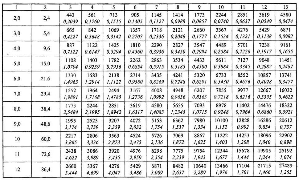

It must be borne in mind that the indicators of the actual air flow in rectangular and round ducts with the same cross-sectional area are not the same even with complete equality of the air flow speeds. If the air temperature exceeds +20°C, then correction factors for friction and local resistance must be used.
The calculation of the ventilation system consists of the calculation of the main line and all branches connected to it. In this case, it is necessary to achieve a position so that the air speed constantly increases as it approaches the suction or discharge fan. If the duct scheme does not allow taking into account branch losses, and their values do not exceed 10% of the total flow, then it is allowed to use the diagram for overpressure damping. The coefficient of resistance to the air flow of the diaphragm is calculated by the formula:

The above duct calculations are suitable for the following types of ventilation:
- Exhaust. It is used to remove exhaust air from industrial, commercial, sports and residential premises. In addition, it can have special filters for cleaning the air emitted from dust or harmful chemical compounds; they can be mounted inside or outside the premises.
- supply. Prepared (heated or purified) air is supplied to the premises, it may have special devices to reduce noise levels, automate control, etc.
- Supply/exhaust. A complex of equipment and devices for supplying/removing air from premises for various purposes may have heat recovery units, which significantly reduces the cost of maintaining a favorable microclimate in the premises.
The movement of air flows through the ducts can be horizontal, vertical or angular. Taking into account the architectural features of the premises, their number and size, air ducts can be installed in several tiers in one room.
Calculation of the cross-sectional area of the pipeline
After the speed of air movement through the air ducts is determined, taking into account the required exchange rate, it is possible to calculate the parameters of the air duct cross section according to the formula S = R\3600v, where S is the air duct cross-sectional area, R is the air flow rate in m 3 / h, v is the speed of air movement flow, 3600 - time correction factor. The cross-sectional area allows you to determine the diameter of a round duct using the formula:
![]()
If a square duct is installed in the room, then it is calculated by the formula d e \u003d 1.30 x ((a x b) 0.625 / (a + b) 0.25).
d e - equivalent diameter for a round duct in millimeters;
a and b are the lengths of the sides of the square or rectangle in millimeters. To simplify the calculations, use the conversion table No. 1.
Table No. 1

To calculate the equivalent diameter of oval ducts, use the formula d = 1.55 S 0.625 /P 0.2
S is the cross-sectional area of the oval duct;
P is the perimeter of the pipe.
The cross-sectional area of an oval pipe is calculated by the formula S \u003d π × a × b / 4
S is the cross-sectional area of the oval duct;
a = large diameter oval duct;
b = smaller diameter of the oval duct.
Selection of oval or square air ducts according to the speed of the air flow To facilitate the selection of the optimal parameter, the designers calculated ready-made tables. With their help, you can choose the optimal size of air ducts of any section, depending on the frequency of air exchange in the premises. The frequency of exchange is selected taking into account the volume of the room and the requirements of SanPin.

Calculation of parameters of air ducts and natural ventilation systems In contrast to forced air supply/removal, for natural ventilation, indications of the difference in pressure outside and inside the premises are important. The drag calculation and direction selection must be done in such a way as to guarantee a minimum flow pressure loss.
When calculating, the existing gravitational pressures are linked with the actual pressure losses in vertical and horizontal air ducts.

Classifications of initial data during the calculation of the cross section of air ducts During calculations, it is necessary to take into account the requirements of the current SNiP 2.04.05-91 and SNiPa 41-01-2003. The calculation of ventilation systems according to the diameter of the air ducts and the equipment used should provide:
- Normalized indicators for air purity, exchange rate and indoor microclimate indicators. The power of the installed equipment is calculated. At the same time, the level of noise and vibration cannot exceed the established limits for buildings and premises, taking into account their purpose.
- The systems must be maintainable, during the scheduled maintenance work, the technological cycle of the enterprises should not be disturbed.
- In rooms with an aggressive environment, only special air ducts and equipment are provided that exclude sparking. Hot surfaces must be additionally insulated.
Standards for design conditions for determining the cross section of air ducts
The calculation of the air duct area should provide:
- Proper conditions for cleanliness and temperature conditions in the premises. For rooms with excess heat, ensure its removal, and in rooms with a lack of heat, minimize the loss of warm air. At the same time, it is necessary to adhere to the economic feasibility of fulfilling these conditions.
- The speed of air movement in the premises should not impair the comfort of people staying in the premises. This takes into account the obligatory air purification in the working areas. In the jet of air entering the room, the speed of movement Nx is determined by the formula Nx = Kn × n. The maximum inlet air temperature is determined by the formula tx = tn + D t1, and the minimum by the formula tcx = tn + D t2. Where: nn, tn - normalized air flow rate in m / s and air temperature at the workplace in degrees Celsius, K \u003d 6 (air velocity transition coefficient at the outlet of the duct and in the room), D t1, D t2 - maximum allowable deviation temperature.
- The maximum concentration of harmful chemical compounds and suspended particles according to GOST 12.1.005-88. Additionally, you need to take into account the latest decisions of the State Supervision.
- Outside air parameters. They are regulated depending on the technological features of the production process, the specific purpose of the structure and buildings. Indicators of the concentration of explosive compounds and substances must meet the requirements of fire-fighting state authorities.
Installation of ventilation systems with forced air supply / removal should be done only in cases where the characteristics of natural ventilation cannot provide the required parameters for cleanliness and temperature conditions in the premises or buildings have separate zones with a complete absence of natural air inflow. For some rooms, the area of the air ducts is selected in such a way that the backwater is constantly maintained in the rooms and the supply of outside air is excluded. This applies to pits, basements and other premises in which there is a possibility of accumulation of harmful substances. Additionally, air cooling must be present at workplaces that have a thermal exposure of more than 140 W/m 2 .
Requirements for ventilation systems If the calculated data on ventilation systems lower the temperature in the premises to + 12 ° C, then it is imperative to provide for simultaneous heating. Heating units of the appropriate power are connected to the systems in order to bring the temperature values up to those normalized by state standards. If ventilation is installed in industrial buildings or public premises in which people constantly stay, then at least two supply and two exhaust constantly operating units must be provided. The size of the area of the air ducts must provide the calculated value of air flows. For connected or adjacent rooms, it is allowed to have two exhaust systems and one supply system, or vice versa.
If the premises must be ventilated around the clock, then backup (emergency) equipment must be connected to the installed air ducts. Additional branches should be taken into account, a separate calculation of the area is made for them. A standby fan can be omitted only if:
- After the failure of the ventilation system, it is possible to quickly stop the work process or take people out of the room.
- The technical parameters of emergency ventilation fully meet the requirements for cleanliness and air temperature in the premises.
General requirements for air ducts The calculation of the final parameters of the air ducts should provide for the possibility of:
- Mounting of fire dampers in vertical or horizontal position.
- Installations on interfloor platforms of air locks. The design features of the devices must ensure that the regulatory requirements for the emergency shutdown of individual branches of the ventilation system and the prevention of the spread of smoke or fire throughout the building are met. In this case, the length of the section on which the gates are attached should not be less than two meters.
- No more than five air ducts can be connected to each floor manifold. The connection node creates additional resistance to air flow, this feature must be taken into account when calculating the dimensions.
- Installation of automatic fire alarm systems. If the alarm drive is mounted inside the duct, then when determining its optimal diameter, the reduction in the effective diameter and the appearance of additional resistance to the air flow due to turbulence should be taken into account. The same requirements are put forward when installing check valves that prevent the flow of harmful chemical compounds from one production facility to another.
Air ducts made of non-combustible materials must be installed for ventilation systems with suction of flammable products or with temperatures above +80°C. The main transit sections of ventilation should be metal. In addition, metal air ducts are mounted in attics, technical rooms, basements and undergrounds.
The total air loss for fittings is determined by the formula:
![]()
Where p is the specific pressure loss per square meter of the expanded section of the duct, ∑Ai is the total expanded area. Within one installation scheme of the ventilation system, losses can be taken from the table.
During the calculation of the dimensions of the air ducts, in any case, engineering assistance will be needed, the employees of our company have enough knowledge to solve all technical issues.
Although there are many programs for calculating ventilation, many parameters are still determined the old fashioned way, using formulas. The calculation of the ventilation load, area, power and parameters of individual elements is carried out after drawing up the diagram and distributing the equipment.
This is a difficult task that only professionals can do. But if you need to calculate the area of some ventilation elements or the cross section of air ducts for a small cottage, you can really do it yourself.
Air exchange calculation

If there are no toxic emissions in the room or their volume is within acceptable limits, air exchange or ventilation load is calculated by the formula:
R= n * R1,
here R1- the need for air of one employee, in cubic meters per hour, n- the number of permanent employees in the premises.
If the volume of the room per employee is more than 40 cubic meters and natural ventilation is working, it is not necessary to calculate the air exchange.
For domestic, sanitary and auxiliary premises, the calculation of ventilation by hazards is carried out on the basis of the approved norms of the air exchange rate:
- for administrative buildings (hood) - 1.5;
- halls (serving) - 2;
- conference rooms for up to 100 people with a capacity (for supply and exhaust) - 3;
- rest rooms: supply 5, extract 4.
For industrial premises in which hazardous substances are constantly or periodically released into the air, the calculation of ventilation is carried out according to hazards.
Air exchange by hazards (vapors and gases) is determined by the formula:
Q= K\(k2- k1),
here TO- the amount of steam or gas appearing in the building, in mg / h, k2- the content of steam or gas in the outflow, usually the value is equal to the MPC, k1- the content of gas or steam in the inflow.
The concentration of hazards in the inflow is allowed up to 1/3 of the MPC.
For rooms with the release of excess heat, air exchange is calculated by the formula:
Q= Ghut\c(tyx – tn),
here Gib- excess heat drawn out, measured in W, from– specific heat capacity by mass, c=1 kJ, tyx- the temperature of the air removed from the room, tn– supply temperature.
Heat Load Calculation

The calculation of the heat load on ventilation is carried out according to the formula:
Qin =Vn*k * p * CR(text -tnro),
in the formula for calculating the heat load on ventilation Vn- external volume of the building in cubic meters, k- air exchange rate, tvn is the average temperature in the building, in degrees Celsius, tnro- outside air temperature used in heating calculations, in degrees Celsius, R- air density, in kg / cubic meter, Wed- heat capacity of air, in kJ \ cubic meter Celsius.
If the air temperature is lower tnro the air exchange rate decreases, and the heat consumption indicator is considered equal to Qv, a constant value.
If, when calculating the heat load on ventilation, it is impossible to reduce the air exchange rate, the heat consumption is calculated from the heating temperature.
Heat consumption for ventilation
The specific annual heat consumption for ventilation is calculated as follows:
Q=*b*(1-E),
in the formula for calculating the heat consumption for ventilation Qo- total heat loss of the building during the heating season, Qb– household heat inputs, Qs- heat input from outside (sun), n- coefficient of thermal inertia of walls and ceilings, E- reduction factor. For individual heating systems 0,15 , for central 0,1 , b– heat loss coefficient:
- 1,11 - for tower buildings;
- 1,13 - for multi-section and multi-access buildings;
- 1,07 - for buildings with warm attics and basements.
Calculation of duct diameter

The diameters and sections of the ventilation ducts are calculated after the general scheme of the system has been drawn up. When calculating the diameters of ventilation ducts, the following indicators are taken into account:
- Air volume (supply or exhaust), which must pass through the pipe for a given period of time, cubic meters per hour;
- The speed of air movement. If, when calculating the ventilation pipes, the flow rate is underestimated, air ducts of too large a section will be installed, which entails additional costs. Excessive speed leads to the appearance of vibrations, increased aerodynamic hum and increased equipment power. The speed of movement on the inflow is 1.5 - 8 m / s, it varies depending on the site;
- Vent material. When calculating the diameter, this indicator affects the resistance of the walls. For example, black steel with rough walls has the highest resistance. Therefore, the calculated diameter of the ventilation duct will have to be slightly increased compared to the norms for plastic or stainless steel.
Table 1. Optimum air flow rate in ventilation pipes.
When the throughput of future air ducts is known, it is possible to calculate the cross section of the ventilation duct:
S= R\3600 v,
here v- the speed of the air flow, in m / s, R- air consumption, cubic meters / h.
The number 3600 is a time factor.
![]()
here: D– diameter of the ventilation pipe, m.
Calculation of the area of ventilation elements
The calculation of the ventilation area is necessary when the elements are made of sheet metal and it is necessary to determine the quantity and cost of the material.
The ventilation area is calculated by electronic calculators or special programs, which can be found in many on the Internet.
We will give several tabular values of the most popular ventilation elements.
| Diameter, mm | Length, m | |||
| 1 | 1,5 | 2 | 2,5 | |
| 100 | 0,3 | 0,5 | 0,6 | 0,8 |
| 125 | 0,4 | 0,6 | 0,8 | 1 |
| 160 | 0,5 | 0,8 | 1 | 1,3 |
| 200 | 0,6 | 0,9 | 1,3 | 1,6 |
| 250 | 0,8 | 1,2 | 1,6 | 2 |
| 280 | 0,9 | 1,3 | 1,8 | 2,2 |
| 315 | 1 | 1,5 | 2 | 2,5 |
table 2. The area of straight circular ducts.
The value of the area in square meters. at the intersection of the horizontal and vertical lines.
| Diameter, mm | Angle, degrees | ||||
| 15 | 30 | 45 | 60 | 90 | |
| 100 | 0,04 | 0,05 | 0,06 | 0,06 | 0,08 |
| 125 | 0,05 | 0,06 | 0,08 | 0,09 | 0,12 |
| 160 | 0,07 | 0,09 | 0,11 | 0,13 | 0,18 |
| 200 | 0,1 | 0,13 | 0,16 | 0,19 | 0,26 |
| 250 | 0,13 | 0,18 | 0,23 | 0,28 | 0,39 |
| 280 | 0,15 | 0,22 | 0,28 | 0,35 | 0,47 |
| 315 | 0,18 | 0,26 | 0,34 | 0,42 | 0,59 |
Table 3. Calculation of the area of bends and semi-branches of circular cross section.
Calculation of diffusers and grilles

Diffusers are used to supply or remove air from a room. The purity and temperature of the air in every corner of the room depends on the correct calculation of the number and location of ventilation diffusers. If you install more diffusers, the pressure in the system will increase, and the speed will drop.
The number of ventilation diffusers is calculated as follows:
N= R\(2820 * v *D*D),
here R- throughput, in cubic meters / hour, v– air speed, m/s, D is the diameter of one diffuser in meters.
The number of ventilation grilles can be calculated using the formula:
N= R\(3600 * v * S),
here R- air consumption in cubic meters / hour, v– air velocity in the system, m/s, S- cross-sectional area of one lattice, sq.m.
Calculation of the duct heater

The calculation of the electrical type ventilation heater is as follows:
P= v * 0,36 * ∆ T
here v- the volume of air passed through the heater in cubic meters / hour, ∆T- the difference between the air temperature outside and inside, which must be provided to the heater.
This indicator varies within 10 - 20, the exact figure is set by the client.
The calculation of the heater for ventilation begins with the calculation of the frontal cross-sectional area:
Af=R * p\3600 * vp,
here R- volume of inflow flow, cub.m.\h, p- density of atmospheric air, kg\cubic meters, vp is the mass air velocity in the area.
The section size is necessary to determine the dimensions of the ventilation heater. If, according to the calculation, the cross-sectional area turns out to be too large, it is necessary to consider the option of a cascade of heat exchangers with a total calculated area.
The mass velocity index is determined through the frontal area of the heat exchangers:
vp= R * p\3600 * Af.fact
For further calculation of the ventilation heater, we determine the amount of heat required to warm the air flow:
Q=0,278 * W * c (TP-Ty),
here W- consumption of warm air, kg / hour, Tp– supply air temperature, degrees Celsius, That- outdoor air temperature, degrees Celsius, c– specific heat capacity of air, constant value 1.005.
Since in supply systems, fans are placed in front of the heat exchanger, we calculate the flow of warm air as follows:
W= R*p
When calculating the ventilation heater, it is necessary to determine the heating surface:
Apn=1.2Q\ k(Ts.t-Ts.v),
here k- heat transfer coefficient of the heater, Tc.t- the average temperature of the coolant, in degrees Celsius, Ts.v– average supply temperature, 1,2 is the cooling factor.
Displacement ventilation calculation
Displacement ventilation in the room is equipped with calculated ascending air flows in places of increased heat generation. Cool clean air is supplied from below, which gradually rises and in the upper part of the room is removed to the outside along with excess heat or moisture.
With proper calculation, displacement ventilation is much more effective than mixing ventilation in the following types of rooms:
- halls for visitors in catering establishments;
- conference rooms;
- any rooms with high ceilings;
- student audiences.
Calculated ventilation displaces less efficiently if:
- ceilings below 2m 30 cm;
- the main problem of the room is increased heat generation;
- it is necessary to lower the temperature in rooms with low ceilings;
- powerful air turbulences in the hall;
- the temperature of the hazards is lower than the air temperature in the room.
Displacement ventilation is calculated based on the fact that the heat load on the room is 65 - 70 W / m2, with a flow rate of up to 50 liters per cubic meter of air per hour. When the heat loads are higher and the flow is lower, it is necessary to organize a mixing system combined with cooling from above.
The key to flawless and efficient operation of ventilation is a competent calculation of the area of air ducts and fittings, which determines the selection of both individual elements and equipment. The purpose of the calculation is to ensure the optimal frequency of air changes in the premises in accordance with their purpose.
In the article, we analyzed in detail each of the mandatory stages of calculations: determining the cross section and the actual area of air ducts, calculating air velocity and selecting the parameters of shaped products. In addition, we outlined the main requirements for the size of ventilation ducts, and also gave an example of calculating air ducts for a private house.
Next, determine the diameters of the ventilation ducts. Since the hood forcibly removes 100 m 3, it remains to distribute the remaining 294 m 3. They will leave naturally through 2 shafts. Each will have: 294: 2 = 147 mᶾ.
Since in the mines of natural ventilation, the air speed ranges from 0.5 to 1.5 m / s, the average value is usually taken in the calculations - 1 m / s. Substituting the known values into the formula S \u003d L: k × V, they find: S \u003d 147: 3600 x 1 \u003d 0.0408 m².
Now it is possible to determine the diameter of a duct with a circle in cross section using the formula: S = (π x D2) : 400 or 0.0408 = (3.14 x D2) : 400.
Having solved this equation with one unknown, by simple calculations, they find that the diameter of the duct is 2.28 mm. Under this value, the nearest larger standard pipe size is selected.
When a rectangular duct is installed, its size is selected according to the table, focusing on the area. The nearest larger value is 200 x 250 mm.
According to the same scheme, the cross-sectional area of \u200b\u200bthe outlet for the kitchen hood is determined with the difference that the air speed here is 3 m / s. S \u003d 100: 3600 x 3 \u003d 0.083 m² or 107 mm in diameter.
A conversion table is necessary when it is necessary to calculate ducts with a rectangular cross section and apply the table for round products. Here are the diameters of ducts with a circle in section, in which the pressure reduction due to friction is equal to the same value in a rectangular design.
There are three ways to determine the equivalent value:
- by speed;
- in cross section;
- by expense.
These values are associated with different duct parameters. For each of them there is an individual method of using tables. The main thing is that, regardless of the method used, the value of the loss of friction pressure is the same.
In conclusion, the speed is checked: V \u003d 147: (3600 x 0.0408) \u003d 1.0 m / s. This is within the allowable limit.
Shaped products and their calculation
When straight sections of various sizes are connected using shaped products.

In the production of both air ducts and fittings, it is necessary to calculate their area. Without this, it is impossible to determine the correct amount of material for the manufacture of parts.
Shaped items include:
- Elbows. They are used to change the direction of the air pipeline at every possible angle. There are both round and rectangular, oval.
- Transitions. With their help, air ducts of various sections are connected. Any geometry - from round to combined.
- Couplings, nipples. Connect straight line segments.
- Tees. Articulate branches or two branches of the duct.
- Stubs. Block the air flow.
- crosses. Separate or connect air streams.
- ducks. Provide a multi-level transition of the duct.

Any shaped product has its own special role in the ventilation system. Manufacturers design each of them separately. They are supplied together with the main elements.
The table shows standard duct sizes. Even professionals use such and similar special tables instead of complex calculations.
Many designers use special programs, online calculators. You only need to enter the primary values and get ready-made parameters at the output.
Programs allow not only to determine the required values of all parts, but also to scan them. This 3D printed scan allows for a perfect fit of the ventilation ducts.
Basic requirements for calculation
When determining the final parameters of the ducts, it must be taken into account that the determination of the area of the ducts must ensure that:
- The temperature regime in the room is provided. Where there is an excess of heat, its removal is provided, and where there is a shortage, its losses are minimized.
- The speed of air movement in no way reduces the level of comfort of people in the room. In areas of working areas, air purification is required.
- Harmful chemical compounds and suspended particles present in the air are in the amount corresponding to GOST 12.1.005-88.
For individual rooms, a prerequisite for selecting the area of air ducts is the constant maintenance of backwater and the exclusion of air supply from outside.

When calculating the resistance of the line, pressure losses are taken into account. In order for the flow of air mass to overcome resistance during movement, appropriate pressure is needed.
Conclusions and useful video on the topic
Online program to help the design engineer:
The plot of the organization of ventilation of a private house as a whole:
The cross-sectional area, shape, length of the duct are some of the parameters that determine the performance of the ventilation system. Correct calculation is extremely important, because. the air throughput, as well as the flow rate and the efficient operation of the structure as a whole, depend on it.
When using an online calculator, the degree of accuracy of the calculation will be higher than when calculating manually. This result is explained by the fact that the program itself automatically rounds the values to more accurate ones.
On this page, using a special calculator, you can make a calculation based on the parameters you set: type, dimensions, thickness of steel. Enter the height, width and length or diameter of the duct (in millimeters), metal thickness (in millimeters).
The calculator will calculate the approximate price of the product with the specified parameters.
Calculation of the cost of rectangular ducts
results
Calculation of the cost of round ducts
results
Pricing
The company "VentSystems" pursues a flexible pricing policy aimed at maintaining the minimum selling price of products for customers. Several factors contribute to this. Firstly, the company sells goods of its own production - all goods are made in their own workshops. Therefore, there are no intermediaries and additional monetary markups. Secondly, all work is carried out on modern high-performance equipment that can produce large volumes in a short period. Such technologies make the production process fast and economical, since even the largest orders do not take so much time to complete.
An important factor for pricing is the supply of raw materials. The material for air ducts and fittings is high-quality sheet steel. It is purchased and delivered to the VentSystems plant regularly and in large volumes from the country's leading suppliers. Long-term contracts with sheet steel manufacturers, long-term cooperation and optimal delivery conditions can significantly reduce costs, which favorably affects the cost of production.
The company's management has built and optimized the process of production and sale of goods in such a way as to exclude causes and sources that could unnecessarily increase the cost of products. All functions and tasks are solved using our own resources without involving additional parties. This makes it possible to confidently maintain a balance between the quality of the proposed ventilation products and their affordable cost. Studies show that there are many offers on the market for similar products with prices significantly higher than those presented by us. The opposite problem is cheap air ducts of dubious quality. The VentSystems company is far from both extremes and offers reliable products that meet all standards at reasonable prices.
Special conditions
For all customers, it is possible to discuss individual terms of cooperation. Regular customers have special discounts and offers. In addition, special conditions for the form and terms of payment may apply to individual orders. Large orders can be paid in installments. All organizational issues can be discussed directly with the management of the enterprise. Enterprise "VentSystems" is always ready for any constructive proposals and is interested in fruitful cooperation with all contractors.
The company's management invites representatives of organizations and interested parties to visit the production complex, inspect the plant's workshops, get acquainted with product samples and negotiate with the management. The office and production complex are located in the village of Yam, Domodedovo district, Moscow region.
Equipping housing with all the benefits of civilization is a necessity for any owner. It is impossible not to include ventilation and air conditioning in the list of engineering systems at home. The arrangement of these complexes must be approached with the utmost responsibility, which is impossible without calculating the area of air ducts and fittings. At the slightest mistake, the microclimate in the room will be disturbed, which will affect the comfort of all family members.
- Calculation of individual zones limited by tees or dampers. If there are branches, then they are added to this segment. The oxygen consumption along the entire length is considered to be stable.
- Determination of the main line with the maximum air consumption. This will be the longest element of the circuit.
- Cross-sections on the calculated sections are selected in accordance with the recommendations of the state standard - ≤ 8 m/s in mains, ≤ 8 m/s in branches, ≤ 3 m/s in blinds and gratings.
- All sections are marked from the least loaded in order of increasing pressure.
- Exhaust, installed on industrial, commercial, sports grounds and in residential buildings, mounted both inside and outside the building.
- Supply air, supplying rooms of various types with prepared air.
- Combined with recovery unit.
- Provide the necessary heating of the mixture and the removal of excess heat at their economic expediency.
- The speed indicators of the movement of air flows should not violate the comfort of being in the premises.
- The limiting concentration of harmful substances, not exceeding the values defined by GOST 12.1.005–88.
- Metal (galvanized, stainless or black steel).
- Made of flexible film (plastic or aluminium).
- Hard plastic.
- Fabrics.
- Drawing up a plan indicating the required amount of air supplied or removed. This is the baseline on which all design work is based.
- Marks on the diagram of individual sections with data on the amount of oxygen moving through them. It is necessary to specify gratings, cross-section differences, bends and valves.
- After selecting the maximum speed, the caliber, diameter or size of the sides of the channel is calculated.
- Branches are ordinary and S-shaped (ducks).
- Adapters in diameter and geometric shape.
- Tees.
- Umbrellas.
- Vent-Calc for calculating cross-sectional area, thrust and resistance in sections.
- GIDRV 3.093 provides control over the calculation of channel parameters.
- Ducter 2.5 selects system elements according to certain characteristics.
- CADvent based on AutoCAD with a maximum database of elements.
Show all
Causes of ventilation problems
If the calculations are made correctly, then the supply of clean air of normal humidity, as well as the removal of unpleasant odors, will be the maximum allowable. Otherwise, the formation of mold, fungus in bathrooms and toilets, constant stuffiness in kitchens and rooms is guaranteed. The situation is aggravated by the fact that almost all rooms are equipped with sealed plastic windows without slot ventilation. We have to compensate for the lack of fresh air forcibly.
Another cause of problems with the elimination of waste masses, unpleasant odors and excess water vapor are blockages and depressurization of ventilation pipes. The redevelopment of premises can have a negative impact on the microclimate if you do not resort to engineering assistance when calculating the area of air ducts when upgrading ventilation in accordance with the new parameters.
The easiest way to fix problems in this system is to check for the presence of traction. To do this, bring a sheet of paper or a burning match to the exhaust channel. The use of open fire in rooms with gas heating equipment is not recommended. If the deviation is clearly noticeable, then there is no need to talk about problems. In the case of the opposite result, it is necessary to find out the reasons for the lack of fresh air supply and proceed to eliminate them, which may require re-calculating all parameters.
Air duct area


Grounds for determining areas
The ventilation communications system is a complex structure. When designing it, it is necessary to calculate the quadrature of rectangular and the cross section of round sections of the network, convert them to square meters. m, calculate the area of tie-ins, transitions. This can be done using special mathematical expressions. or a special program - an online calculator for calculating air ducts.


Formula calculation
There are several definitions for making calculations. The main ones are:

MagiCAD duct area


Sequence of operations
In order not to be mistaken in the projected indicators, it is necessary to break the entire work cycle into stages. Approximately the following sequence will turn out:
Given the preconditions, it is possible to calculate the performance of ventilation systems. The formulas to be used are:

It is assumed that special reference books will be used during the calculations. They indicate the practical losses due to friction, air consumption at various flow rates:

A diaphragm is used to dampen excess pressure. The coefficient of its resistance is determined as follows:

The data from these tables is used for several types of ventilation installations. Among them:
Calculation of pressure drop in ducts
Calculation of the diameter of the channels
Having determined the speed of the air masses inside the route, we can proceed to the calculation of the next parameter. It is determined by the formula S=R\3600v, where S is the cross-sectional area of the line, R is the cost of oxygen in m3/h, v is the speed of the air flow, 3600 is the time correction factor. Having learned it, the diameter is calculated:
When determining the size of the main pipelines, certain conditions must be met. The project must meet the following criteria:
Basic concepts of aerodynamic calculation LESSON 1 (total 10 lessons)
Channel types
Before you start calculating air ducts and fittings, you need to know what material they are made of. The recalculation of the cross-sectional area and the manner of movement of air masses inside depend on this. Channels for ventilation are:
Their shape is mainly rectangular or round, less often - oval. They are made at industrial enterprises, since it is quite difficult to organize production directly at the facility.
Diameter definition
This task becomes the main one when creating design documentation for the ventilation system. The process can be carried out both by specialist installers and independently, using the calculator of air ducts and fittings. This can be done in two ways.
The variant with the use of allowable speeds is based on the normalized speed of movement inside the pipe. The indicators are selected for a particular type of premises and a section of the highway according to the recommended values.
Each building is characterized by the maximum permitted rate of air distribution, which is unacceptable to exceed. For regular use, you should take this scheme:
Simple calculation of ventilation with a heat exchanger.
And also you can select these parameters according to the method of determining pressure losses, summing them up on indirect sections and bends, gratings and tees. This will require geometric formulas and special tables.
Material selection
This procedure is performed at the facility that manufactures the duct and accessories. In this case, the quantity of raw materials for the production of the required quantity of products is determined. For such purposes, a profile development is created and formulas from geometry are used. For round sections, this will be the diameter of the pipe multiplied by the circumference.
Shaped products are more difficult to calculate, since there are no ready-made formulas for them. You have to produce for each element separately. It is not possible to carry out the operation on site, therefore all additional parts are supplied by the manufacturer together with the main structural elements.
The most common components for ventilation and air conditioning systems are:

Each of these components has a special role in the ventilation system complex, so each of them is designed separately. It is not difficult to calculate both shaped products and the area of air ducts with an online calculator.
Assistance Programs
To eliminate human factors in the calculations, as well as reduce the design time, several products have been developed that allow you to correctly determine the parameters of the future ventilation system. In addition, some of them allow the construction of a 3D model of the complex being created. Among them are the following developments:
Everyone solves the problem of selecting the dimensions of future ventilation independently. For an inexperienced installer, it will be preferable to design and install all components with the help of specialists who have experience in creating such highways and the appropriate equipment and fixtures.