What you need for a DIY laser engraver. Homemade CNC laser engraver from stones and sticks
Step 6: Preparing the arduino
When I took up arduino, I started by writing my own software.
But as I started looking for ways to control motion via the serial port, I came across something called "GRBL". It turns out this is a g-code interpreter with a large number interesting features.
I had everything already connected to the arduino and so I had to do one of two things: either swap the connections or change something in the code
It turned out that it is much easier to change the control pins in the program.
IMPORTANT:
The current version of Grbl (0.6b) has a bug in the queuing system. The laser turns on and turns off immediately (M3, M5).
The commands are not queued and the laser turns on and off immediately as soon as the arduino receives the commands.
This will be decided - but I can’t say exactly when... Instead, we do this:
you can use the source from here, or just take a ready-made compiled hex. the file I used is . This should solve this problem until it comes out new version Grbl.
No matter which path you choose, you must end up with a hex. file that you should load later into arduino.
I tried a few different ways, and the one I liked best was when I used the Xloader program.
Programming is pretty straightforward.
Select the correct serial port for arduino.
Select hex. file, then arduino type, then click on upload.
If you use a new one arduino uno, then Xloader will not work and you will get a loading error.
So I recommend using ARP/Arduino Uploader - but even this uploader has some problems with arduino uno.
At arduino programming, - select the com port and the type of your arduino (what model is it - the full name so that the program understands how to work with it) in the corresponding drop-down list.
After this, you must make changes to the "avr dude params" text.
Erase "-b19200" - without quotes and click on the download button.
Either way, in a couple of seconds you'll be done and ready to experience.
Exit Xloader and go to the next paragraph.
The Arduino must be configured to get started. Open your favorite terminal window and open the port your arduino is connected to.
There you should see a welcome message:
Grbl 0.6b
"$" to dump current settings"
If you enter $ followed by return you will get a list of options. Something like this:
$0 = 400.0 (steps/mm x)
$1 = 400.0 (steps/mm y)
$2 = 400.0 (steps/mm z)
$3 = 30 (microseconds step pulse)
$4 = 480.0 (mm/sec default feed rate)
$5 = 480.0 (mm/sec default seek rate)
$6 = 0.100 (mm/arc segment)
$7 = 0 (step port invert mask. binary = 0)
$8 = 25 (acceleration in mm/sec^2)
$9 = 300 (max instant cornering speed change in delta mm/min)
"$x=value" to set parameter or just "$" to dump current settings
ok
Grbl 0.6b
"$" reset current settings"
If you enter $ you will get a list of options. Something like this:
$0 = 400.0 (steps/mm x)
$1 = 400.0 (steps/mm y)
$2 = 400.0 (steps/mm z)
$3 = 30 (microseconds per step pulse)
$4 = 480.0 (mm/sec default feed rate)
$5 = 480.0 (mm/sec default search speed)
$6 = 0.100 (mm/arc segment)
$7 = 0 (step port invert mask. binary = 0)
$8 = 25 (acceleration in mm/sec^2)
$9 = 300 (max instantaneous turn speed change in delta mm/min)
"$x=value" set a parameter or simply "$" reset the current settings
ok
You have to change the steps/mm for both o53.333 - for both. Simply enter "$0=53.33", followed by return, and then "$1=53.333", followed by return. The Z axis can be ignored - since we are not using it. Acceleration can be increased to 100 (“$8=100” and back). Since the car is moving slowly, the acceleration can be set high. To others side effect Low acceleration may be that curves can be burned out more than straight lines as the controller is constantly trying to speed up and slow down and never reaches full speed.
If you build the device the same way as I do, then the following error may appear: one of your axes will be mirrored. But this is easy to fix. Option $7 gives you the ability to change the direction of the axis. I would like to change the direction of the X axis, so I entered: "$7=8" since I wanted to change the bitness to 3 (8 = 00001000 binary). If you want to change the direction of the Y axis, you need to enter 16 (00010000) or 24 (00011000) to change both.
Full documentation on mask inversion can be found here
So. We stopped drinking, we’ve already assembled the milling cutter, we bought an Arduina, our arms are gradually straightening - soon we’ll be completely like Homo Sapiens. And he, as you know, is used to creating problems for himself on his own, like a Chinese Komsomol member, and then solving them. Such is the Russian character.
From "nothing" we will need:
Arduino Uno
Shield with a pair of StepSticks
Laser.....as an option it’s easier to purchase, but if you have an inquisitive mind, you can pick up a DVD
Two old CD/DVD ROMs, better than the old ones
Power supply 12 volts....amps so little 2-3-5-10 it doesn’t matter at all
A little drill, a few M4 and M3 screws
Two pieces of square pipe 20x20mm and 180mm long
Chip ULN2003 letters can be different - for us the numbers 2003 are important. This chip is often used in old Mastek scanners to control the stepper motor.
In general, the real owner of such rubbish usually has plenty....
If you don’t find Arduino in the house, you can search, for example, on Avito or AliExpress
It’s better to order the shield in advance too... for example 3D Printer Engraving Machine A4988 Drive Extension Board CNC Shield V3 For Arduino + StepStick 2 pcs walkera new v120d02s 6ch 3d rc remote control helicopter bnf green (Red)
If for some reason there is no laser in the trash, you can look for it here: 405nm 50mW Focusable Violet Dot Laser Module Laser Generator Diode Focusable Laser Module Red Dot Laser Generator Diode 200-250mW 650nm , 450-500mW Violet Laser Module With Holder For Mini Engraving Machine And suddenly it was time for horror stories.Friends, when dealing with a laser, beware of direct and even reflected eye contact. laser beam. You can lose your sight forever. It is best to carry out all work wearing special glasses, which are always sold in departments selling laser lasers. diodes.
Well, if you can’t wait until the Chinese send the long-awaited package, you can experiment with a laser diode from DVD-RW. I'll stop at the last one. When disassembling a recordable DVD, be careful - it usually uses two diodes - one with a visible (usually red) radiation spectrum, the second with an invisible infrared one. I highly recommend not using the second one in terms of security.
To test the LED, we connect a regular 1.5 volt battery to it. If the radiation is red, everything is ok. .1421879657252.prev.jpg)
Let's start messing around....excuse me...disassembling the CD-roms. Straighten the paperclip and push it into the hole in the front of the device. The disk compartment will open, remove the compartment cover and remove the screws. Then everything is the same as everywhere else.

I immediately glued the compartment lid to the front panel

We throw out the tray, the boards, and in general free up the internal space of the former DVD case as much as possible. This is where we will subsequently install the power supply

I plugged in the power supply from some HP printer, converting it from 38 volts to 12. Its power is enough for the eyes.
Then it’s even simpler - we dig out a couple of strong magnets from the DVD (in the lens block), glue them to the laser. We try not to heat it too much when gluing with a heat gun.
We drill and saw square pipe blanks.

Drill out holes Ø4mm on the front side and on the other side to 10mm
We screw it to the DVD-Yuka body.
Using rubber dampers from the DVD itself, we screw the linear drives to the body.


We get something like.....
We cut a strip of steel from the second DVD case and glue it to the horizontal linear module with a heat gun - as in the photo (we attach the laser to it using magnets)
On the lower drive, again using hot glue, we glue a piece of plexiglass/plastic 4mm thick and approximately 45x35mm in size. We glue the desktop to it using superglue with an activator. I cut it out of the body of an old 3.5" floppy
We try to glue the table strictly horizontally.
WITH reverse side We shoot a piece of plastic or plexiglass onto the rivets - we will attach the electronics to it with double-sided tape.
Yes, I almost forgot - I attached the linear modules to rubber bushings from some old printers - it is quite possible to use any suitable tubes - for example, cut an old felt-tip pen evenly.
So we got to the electronics. It's actually simple
Despite the fact that the nameplate says 12-36 volts, it should be powered with 12 volts.
If the motors spin in the opposite direction, simply turn off the power and turn the connector 180 degrees.
The connector has pinout AaBv (beginning of the first winding, end of the first winding, beginning of the second winding, end of the second winding)
The laser is powered and controlled by the 2003 chip. Only four outputs of the chip are used.
The program itself
(Mylaser.zip)
HEX firmware
(grbl_v0_8c_atmega328p_16mhz_9600.hex.rar)
Arduino firmware
(grbl-master.rar)
GRBL controller program
(GrblController361Setup.rar)
It is very important to upload the firmware to the Arduino with a bitrate of 9600. With a different bitrate, the program simply will not see the Arduino.
It is necessary to fill in the EEPROM with the “step per mm” values; steppers in SD/DVD ROMs usually have 20 steps per revolution. StepSticks usually use a multiplier of 1/16 - i.e. 320 steps. The drive usually travels 3mm per revolution (you need to measure the distance between the turns on the drive screw). 320/3 = 106 steps per 1 mm.
We enter this value using command line in the GRBL Controller program
$100=106 (Enter)
$101=106 (Enter)
$102=106 (Enter)
You can upload the firmware to Arduino Uno using the Arduino program. way:
Unpacking the archive
Rename (for example, just to GRBL)
Copy to the "library" folder
Open the program, menu Sketch - load library - select GRBL.1421957319229.prev.jpg)

PS the workpiece is attached to the desktop using the same magnets from the DVD head
PPS laser focusing is done by raising/lowering the diode relative to the table. For this purpose, we have provided a magnetic mount.
Attention! Be careful when using lasers. The laser used in this machine may cause vision damage and possibly blindness. When working with powerful lasers above 5 mW, always wear a pair of safety glasses designed to block the laser wavelength.
A laser engraver on Arduino is a device whose role is to engrave wood and other materials. Over the past 5 years, laser diodes have advanced, allowing fairly powerful engravers to be made without much of the complexity of operating laser tubes.
You should be careful when engraving other materials. For example, when using plastic with a laser device, smoke will appear that contains dangerous gases when burned.
In this lesson I will try to give some direction to the thought, and over time we will create more detailed lesson for the implementation of this complex device.
To begin with, I suggest you look at what the entire process of creating an engraver looked like for one radio amateur:
Strong stepper motors also require drivers to get the most out of them. In this project, a special stepper driver is used for each motor.
Below is some information about the selected components:
- Stepper motor – 2 pieces.
- Frame size is NEMA 23.
- Torque is 1.8 lb-ft at 255 oz.
- 200 steps/revolutions – 1 step 1.8 degrees.
- Current – up to 3.0 A.
- Weight – 1.05 kg.
- Bipolar 4-wire connection.
- Stepper driver – 2 pieces.
- Digital stepping drive.
- Chip.
- Output current – from 0.5 A to 5.6 A.
- Output current limiter – reduces the risk of motor overheating.
- Control signals: Step and Direction inputs.
- Pulse input frequency – up to 200 kHz.
- Supply voltage – 20 V – 50 V DC.
For each axis, the motor directly drives the ball screw through the motor connector. The motors are mounted on the frame using two aluminum corners and an aluminum plate. The aluminum corners and plate are 3mm thick and are strong enough to support a 1kg motor without bending.
Important! The motor shaft and ball screw must be properly aligned. The connectors that are used have some flexibility to compensate for minor errors, but if the alignment error is too large, they will not work!
Another creation process of this device you can watch the video:
2. Materials and tools
Below is a table with the materials and tools needed for the project " laser engraver on Arduino."
| Paragraph | Supplier | Quantity |
| NEMA 23 stepper motor + driver | eBay (seller: primopal_motor) | 2 |
| Diameter 16mm, pitch 5mm, ball screw 400mm long (Taiwanese) | eBay (seller: silvers-123) | 2 |
| 16mm BK12 support with ball screw (drive end) | eBay (seller: silvers-123) | 2 |
| 16mm BF12 Ball Screw Support (No Driven End) | eBay (seller: silvers-123) | 2 |
| 16 shaft 500 mm long | (seller: silvers-123) | 4 |
| (SK16) 16 shaft support (SK16) | (seller: silvers-123) | 8 |
| 16 linear bearing (SC16LUU) | eBay (seller: silvers-123) | 4 |
| eBay (seller: silvers-123) | 2 | |
| Shaft holder 12 mm (SK12) | (seller: silvers-123) | 2 |
| A4 size 4.5mm clear acrylic sheet | eBay (seller: acrylicsonline) | 4 |
| Aluminum Flat Rod 100mm x 300mm x 3mm | eBay (seller: willymetals) | 3 |
| 50mm x 50mm 2.1m Aluminum Fence | Any theme store | 3 |
| Aluminum Flat Rod | Any theme store | 1 |
| Aluminum corner | Any theme store | 1 |
| Aluminum corner 25mm x 25mm x 1m x 1.4mm | Any theme store | 1 |
| M5 socket head screws (various lengths) | boltsnutsscrewsonline.com | |
| M5 nuts | boltsnutsscrewsonline.com | |
| M5 washers | boltsnutsscrewsonline.com |
3. Development of the base and axes

The machine uses ball screws and linear bearings to control the position and movement of the X and Y axes.
Characteristics of ball screws and machine accessories:
- 16 mm ball screw, length – 400 mm-462 mm, including machined ends;
- pitch – 5 mm;
- C7 accuracy rating;
- BK12/BF12 ball joints.
Since the ball nut consists of ball bearings rolling in a track against a ball screw with very little friction, this means that motors can run at higher speeds without stopping.
The rotational orientation of the ball nut is locked using aluminum element. The base plate is attached to two linear bearings and a ball nut through aluminum corner. Rotation of the Ballscrew shaft causes the base plate to move linearly.
4. Electronic component

The laser diode selected is a 1.5 W, 445 nm diode housed in a 12 mm package with a focusable glass lens. These can be found, pre-assembled, on eBay. Since it is a 445 nm laser, the light it produces is visible blue light.
The laser diode requires a heatsink when operating at high levels power. When constructing the engraver, two aluminum supports for SK12 12 mm are used, both for mounting and for cooling the laser module.
The output intensity of a laser depends on the current that passes through it. A diode by itself cannot regulate current, and if connected directly to a power source, it will increase current until it is destroyed. Thus, to protect the laser diode and control its brightness, it is required adjustable circuit current
Another option for connecting the microcontroller and electronic parts:

5. Software
The Arduino sketch interprets each command block. There are several commands:
1 – move RIGHT one pixel FAST (blank pixel).
2 – move RIGHT one pixel SLOW (burnt pixel).
3 – Move LEFT one pixel FAST (blank pixel).
4 – Move LEFT one pixel SLOW (burnt pixel).
5 – move up one pixel FAST (empty pixel).
6 – Move UP one pixel SLOW (burnt pixel).
7 – Move DOWN one pixel FAST (blank pixel).
8 – move DOWN one pixel SLOW (burnt pixel).
9 – turn on the laser.
0 – turn off the laser.
r – return the axes to their original position.
With each character, the Arduino runs the corresponding function to write to the output pins.
Arduino controls engine speed through delays between step pulses. Ideally, the machine will run its motors at the same speed whether it is engraving an image or passing a blank pixel. However, due to the limited power of the laser diode, the machine must slow down at pixel records. That's why there is two speeds for each direction in the list of command symbols above.
A sketch of 3 programs for the Arduino laser engraver is below:
/* Stepper motor control program */ // constants won't change. Used here to set pin numbers: const int ledPin = 13; // the number of the LED pin const int OFF = 0; const int ON = 1; const int XmotorDIR = 5; const int XmotorPULSE = 2; const int YmotorPULSE = 3; //half step delay for blank pixels - multiply by 8 (<8ms)
const unsigned int shortdelay = 936;
//half step delay for burnt pixels - multiply by 8 (<18ms)
const unsigned int longdelay = 2125;
//Scale factor
//Motor driver uses 200 steps per revolution
//Ballscrew pitch is 5mm. 200 steps/5mm, 1 step = 0.025mm
//const int scalefactor = 4; //full step
const int scalefactor = 8; //half step
const int LASER = 51;
// Variables that will change:
int ledState = LOW; // ledState used to set the LED
int counter = 0;
int a = 0;
int initialmode = 0;
int lasermode = 0;
long xpositioncount = 0;
long ypositioncount = 0;
//***********************************************************************************************************
//Initialisation Function
//***********************************************************************************************************
void setup()
{
// set the digital pin as output:
pinMode(ledPin, OUTPUT);
pinMode(LASER, OUTPUT);
for (a = 2; a <8; a++){
pinMode(a, OUTPUT);
}
a = 0;
setinitialmode();
digitalWrite (ledPin, ON);
delay(2000);
digitalWrite (ledPin, OFF);
// Turn the Serial Protocol ON
Serial.begin(9600);
}
//************************************************************************************************************
//Main loop
//************************************************************************************************************
void loop()
{
byte byteRead;
if (Serial.available()) {
/* read the most recent byte */
byteRead = Serial.read();
//You have to subtract "0" from the read Byte to convert from text to a number.
if (byteRead!="r"){
byteRead=byteRead-"0";
}
//Move motors
if(byteRead==1){
//Move right FAST
fastright();
}
if(byteRead==2){
//Move right SLOW
slowright();
}
if(byteRead==3){
//Move left FAST
fastleft();
}
if(byteRead==4){
//Move left SLOW
slowleft();
}
if(byteRead==5){
//Move up FAST
fastup();
}
if(byteRead==6){
//Move up SLOW
slowup();
}
if(byteRead==7){
//Move down FAST
fastdown();
}
if(byteRead==8){
//Move down SLOW
slowdown();
}
if(byteRead==9){
digitalWrite (LASER, ON);
}
if(byteRead==0){
digitalWrite (LASER, OFF);
}
if (byteRead=="r"){
//reset position
xresetposition();
yresetposition();
delay(1000);
}
}
}
//************************************************************************************************************
//Set initial mode
//************************************************************************************************************
void setinitialmode()
{
if (initialmode == 0){
digitalWrite (XmotorDIR, OFF);
digitalWrite (XmotorPULSE, OFF);
digitalWrite (YmotorDIR, OFF);
digitalWrite (YmotorPULSE, OFF);
digitalWrite (ledPin, OFF);
initialmode = 1;
}
}
//************************************************************************************************************
// Main Motor functions
//************************************************************************************************************
void fastright()
{
for (a=0; a
6. Launch and setup
Arduino represents the brain for the machine. It outputs the step and direction signals for the stepper drivers and the laser enable signal for the laser driver. In the current project, only 5 output pins are required to control the machine. It is important to remember that the bases for all components must be related to each other.
7. Functionality check
This circuit requires at least 10VDC power, and has a simple on/off input signal provided by the Arduino. The LM317T chip is a linear voltage regulator that is configured as a current regulator. The circuit includes a potentiometer that allows you to adjust the regulated current.
In the previous article I described the experience of assembling and setting up an engraver from a Chinese kit. After working with the device, I realized that it would not be out of place in my laboratory. The task has been set, I will solve it.
There are two solutions on the horizon - ordering a kit in China and developing your own design.
DESIGN DISADVANTAGES WITH ALIEXPRESS
As I wrote in the previous article, the set turned out to be quite functional. The practice of working with the machine revealed the following design flaws:
- The design of the carriage is poorly designed. This is clearly visible in the video in the previous article.
- The rollers of the moving units are mounted on the panels with M5 screws and are connected to the panel on only one side. At the same time, no matter how you tighten the screws, there remains some play.
PLASTIC PARTS
Since the frame made from a machine-made profile is quite decent, it was possible to eliminate the identified shortcomings by recycling the plastic parts.
I described the laser holder quite well in. I also added an additional piece to the design that connects all four rollers on the right and left panels. This detail made it possible to eliminate play when moving panels.
All parts have fairly simple shapes and do not require supports or other difficulties when printing.
To order a set of plastic parts, you need to go to the online store:
Models of plastic parts for printing are available:
DEMONSTRATION OF WORK
The engraver's work and appearance can be assessed in the following video.
ENGRAVER CONSTRUCTION
The frame of the engraver is built on a machine-made aluminum profile 20x40. The parts supporting the moving parts of the engraver are made on a 3D printer. The moving parts move on standard rollers. The carriage carrying the laser module allows you to adjust the height of the laser above the desktop, which allows you to focus the power of the laser beam in a fairly large range.
The assembly of the structure is shown in 3D PDF format.
ASSEMBLY
The design is very simple. For this reason, assembly will not take much time and pain if you follow the recommended assembly sequence.
STEP 1. FRAMEWORK
As described above, the frame is constructed from 20x40 structural profile. To twist the profile together, internal corners are used.
On longer parts, threads are cut in the central holes of the ends for mounting legs and side panels (on the middle length).

The frame is twisted at the corners, with short parts inward. At this stage, you should not fully tighten the screws - it is better to do this after installing the legs.

The legs are secured with screws at four points. This is done so that the frame is assembled without possible distortions.

First you need to secure all four legs, again without fully tightening the fasteners.

Now you need to find the most flat surface possible! Arrange all the parts so that the frame “stands” tightly, without playing on the surface.

We stretch all the fasteners, starting from the inner corners and controlling possible distortions with a square.

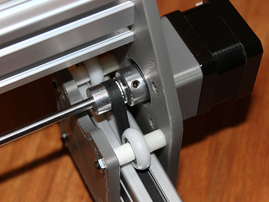
STEP 2. RIGHT PANEL
Before assembling the right panel, a flexible coupling must be installed on the motor shaft.

Then you need to screw the stepper motor through a plastic spacer.

The position of the cable outlet and the spacer are clearly visible in the figure below.

STEP 3. LEFT PANEL
To assemble the left panel, you only need to press the bearing into the hole.

I tried to eliminate the gluing operation. To do this, he “sent a wave” along the surface of the hole for installing the bearing. For this reason, it is necessary to press the bearing firmly.

STEP 4. INSTALLATION OF THE LEFT PANEL


Then install the assembly on the profile.

And secure the lower rollers. The figure clearly shows that the mounting holes of the screws for fastening the rollers have a stroke of several millimeters. This is done so that the upper and lower rollers can be tightly tightened on the profile, eliminating play. The only thing is that you need to act carefully and not overtighten. In this case, the stepper motor will require excessive force to move the panels.

STEP 5. INSTALLING THE RIGHT PANEL
The following parts will be required for installation.

First you need to install the top rollers.

Then install the assembly on the profile and install the lower rollers. Further installation is identical to the installation of the left panel.

After tightening the screws, you will need to check the progress of the panel. It should move quite easily and there should be no play.

STEP 6. INSTALLING THE GUIDE CARRIAGE
This design uses both panels to transmit movement along the Y axis. In order not to use 2 stepper motors, torque is transmitted to the left panel through a shaft with a diameter of 5 mm. After preparing the details, we begin.

First, the coupling shaft is installed and clamped with the flexible coupling locking screws.

During installation, it is necessary to ensure that the pulleys are not forgotten. There is no need to secure them rigidly at the moment. Adjustment will be required when tightening the belts.

STEP 7. CARRIAGE
The carriage assembly is discussed in detail in the previous article...

Assembly is not particularly difficult.

STEP 8. INSTALLING THE CARRIAGE ON THE RAIL
First you need to collect all the necessary parts.

All installation operations are identical to the panel installation operations.

STEP 9. INSTALLATION OF BELTS
The belts are tightened with screws under the profile nuts. You will need to cut 3 straps in place and prepare the fasteners.

To begin with, the edge of the belt is located in the profile niche with the tooth down. After this, the nut is installed. It will take some force to install the nut.

When tensioning the belt, you will need to set the position of the pulley. The pulley is positioned so that throughout the entire run the belt rubs against the side edges of the pulley as little as possible.
To install the guide carriage belt, it is better to lift it as shown in the figure below, since it is still better to install the nuts into the niche from the end.

Afterwards the guide is lowered to its normal place.

Before tightening the second “tail” of the belt, you must make sure that the belt is tensioned sufficiently.

This completes the assembly of mechanics.

CONTROLLER
I plan to prepare a description of the controllers for controlling the engraver in a separate article. Follow the publications!
ASSEMBLY KIT AND TURNKEY LASER ENGRAVER
Since December 2017, I have been accepting orders for a complete assembly kit and an assembled, configured and completely ready-to-use laser engraver described in the article. Information is available in the online store.
If the article helped you and you want to support new projects, link for support:

Engravers are widely used in various industries not only for engraving various materials, but also for drilling miniature holes, polishing, grinding, and milling. The same operations can be performed at home with their help. If this is only required occasionally, or you just need to save money on buying a tool, then you can make a mini-drill yourself from unnecessary equipment, which often lies unused in garages or storage rooms. With the help of homemade drills, you can perform the same operations as with a factory tool of similar power, you just need to use the appropriate attachments.
Based on the features of their functioning, engravers are divided into milling and laser. In the first, the material is processed with various attachments. In laser models, all the work is done by the laser beam - this contactless engraving method. Moreover, such a device belongs to the category of high-tech equipment. But a homemade engraver can be made at home.
To create a laser engraver with your own hands, you will need the following parts, tools and materials:
- stepper motors from a DVD drive;
- Arduino computing platform;
- Proto Board with display;
- limit switches for motors;
- laser module (for example, 3 W power);
- device for adjusting the constant voltage value;
- laser cooling system;
- MOSFET (transistor);
- boards for assembling electric motor control elements;
- frame;
- toothed pulleys and belts for them;
- bearings of various sizes;
- wooden boards: 2 pieces measuring 135x10x2 cm and two more - 125x10x2 cm;
- 4 round metal rods with a cross section of 10 mm;
- lubricant;
- clamps, bolts with washers and nuts;
- vice;
- locksmith tools;
- drills;
- jigsaw or circular saw;
- files or sandpaper;
- computer or laptop.
Stepper motors can be taken not only from a DVD, but also from a printer that is practically not used.
The machine is assembled according to the following algorithm:
- create a foundation;
- install guides with movable carriages;
- assemble an electrical circuit;
- install the necessary programs on the computer;
- carry out adjustment (tuning) of the laser head;
- check the functionality of the machine.
Connection diagram Stepper electric motors taken from an inkjet printer or DVD are shown in the photo below.
The entire sequence of actions that allows you to assemble a laser engraver using Arduino is demonstrated in detail in the video below.
The created CNC engraver will cost much cheaper than any factory-produced laser models. It can be used for making stamps, for photoresist, for working with wood, plywood, plastic, cardboard, polystyrene foam and cork sheets. Metal engraving is also possible.
Assembling an electric engraver with a tripod and flexible shaft
An electric engraver is the most common type of this type of tool at home. To make a functionally complete device yourself, capable of competing with industrially produced analogues, you will need an electric motor that runs on 220 V alternating current. Such electric motors can be taken from the following equipment:
- Soviet-style reel-to-reel tape recorders;
- DVD players;
- washing machines;
- angle grinders;
- electric sewing machines.
The last option is optimal because it is possible to adjust the speed over a fairly wide range using the built-in rheostat.
For domestic use, a drill with an idle engine speed of up to 6 thousand revolutions per minute is sufficient.
Holding an electric motor from any of the listed types of equipment in one hand is inconvenient, and in most cases it is simply impossible. Therefore you will need flexible shaft for engraver. In this case, the general view of the future device will turn out approximately as in the photo below.

The functionality of the created engraving device will depend on the materials and mechanisms used during assembly. The motor can be placed on the table, but it is more convenient to do it tripod for engraver, or rather its likeness.
Manufacturing of flexible shaft
With a flexible shaft everything is relatively simple. It can be done in several ways:
- from an old drive shaft, for example, from a dental drill;
- using the speedometer cable of a motorcycle or car.
The working shaft attachment can also be used from a drill or make it yourself from different materials, for example, wood, textolite, plastic pipes. From textolite The device (handle) for holding the equipment is made like this:
- cut 2 textolite platinums (sheet thickness should be about 1 cm) measuring approximately 2 by 10 cm;
- connect them together and grind them with a file or emery from the outside to form a cylinder;
- grooves are machined from the inside;
- metal rings secure the parts to each other;
- a tube is inserted into the front part of the handle, under a cartridge consisting of two separate halves connected with a bolt.
The end result will be a handle like the one in the photo below.
The internal hole made between the textolite plates should be of such a cross-section as not to interfere with the free rotation of the cable. It will be possible to insert nozzles with shank diameters from 2 to 5 mm into the chuck.
Assembling the engraving unit
It’s very easy to make a tripod (a base for installing an electric motor) from plywood or the same PCB. To do this, do this:
- cut out several pieces (4 are enough) from a sheet of material corresponding to the size of the electric motor;
- a motor is attached to one of the fragments using clamps;
- assemble the box;
- A hole is drilled in the front part for the flexible shaft.
The created structure is hung on the wall.

Convenient to use factory holder with clamps for the engraver, if the dimensions of the electric motor allow. The mount connects to any table. But such a device will need to be purchased additionally.
Further assembly of the engraving device is carried out in the following sequence:
- using a coupling made from a drilled bolt, connect the cable to the electric motor shaft;

- put a rubber hose of the appropriate diameter on the cable and attach a handle made to it;

- install a start button;
- connect equipment to the network;

- check the functionality of the device made.
A homemade drill will allow you to process wood, bone, metal, glass, plastic, ceramic workpieces, as well as various metals, natural and artificial stone.
You can also use electric motors when creating homemade straight grinders, designed for 380 V, but if they can be adjusted to 220. In such cases, you will need to tinker a little more. There is a lot of information on this issue both on the Internet and in books on electrical engineering.
Making a mini drill from a motor
It happens that at home you need to make small holes in wood or plastic, and drill bits are not suitable. In such cases, a homemade mini-drill made from a motor will help. It can also be used to perform wood engraving. And if you are interested in amateur radio, then using the created tool you can drill and cut boards.
To create a homemade device, you will need to take a miniature electric motor from an old tape recorder. Even various models of motors from children's toys are suitable. If you use a mini-motor from a 12 V tape recorder as a drive, you will also need the following materials and parts:
- power supply or several batteries (battery) with 12 V output;
- a piece of plastic pipe (about 10 cm long) with such a cross-section that a miniature electric motor can be inserted inside;
- heat-resistant glue;
- power button;
- wiring for electrical connections.
You can assemble a mini-drill yourself using the following algorithm:
- using an electric drill or knife, make a hole in the tube for the switch;
- lubricate the motor with glue to fix it inside the future housing;

- insert the electric motor into the tube;
- any of the wires through which the motor is powered is inserted into a hole previously drilled in the housing, and the other end is left on the back side of the housing;

- insert one wire from the power supply into the hole under the button;
- solder the switch to the protruding ends using a soldering iron, carefully insulating the contacts;

- The two remaining wires from the end of the tube (from the button and the motor) are connected to the connector for connecting the power supply;

- cut off the neck of any plastic bottle;
- make a hole in the center of the cover for the connector and glue these parts together;
- glue the neck to the tube;

- connect the assembled mini drill to the power supply;

- By pressing a button, they check the functionality of the homemade product.
Power supply voltage should be selected so that it matches the operating voltage of the electric motor used.
To make a mini drill autonomous, you just need to attach batteries to it.
Homemade Dremel from a drill and blender
If you have an old or unnecessary blender, then it is also easy to make a mini-drill from it. This household appliance already has a comfortable handle. In addition to the blender itself, you will also need the following devices and additional parts:
- tools to disassemble the device (screwdrivers with different tips, pliers);
- caliper or ruler;
- collet;
- soldering iron with soldering kit;
- finishing file, sandpaper;
- switch.
You can do without the last part, but then you will need to constantly press the power button with your hand while working with the straight grinder.
An engraver from a blender is created like this:
- carefully disassemble household appliances;
- they take out the internal parts: the electric motor and the printed circuit board that controls the operation of the device;
- using a caliper, measure the diameter of the spindle in order to purchase a collet chuck suitable for it;
- if the electric motor is contaminated with anything, for example, rust, then it is cleaned thoroughly, with care so as not to damage the windings;
- fix the purchased collet chuck (or one made independently) on the spindle;
- the power button already on the blender is replaced with a switch: the wire contacts are soldered;
- adapt a hole in the body of the household appliance for a new switch;
- install the electric motor with the board in its place inside the housing;
- collect the tool.
Depending on the model of the blender you are converting, you may need to do additional holes in its body, or expand existing ones using a file. There will be no problem doing this
The entire described process of assembling a Dremel from a blender is demonstrated in detail in the video below.
You don’t have to remake the blender, but simply connect to it a flexible shaft for a factory-made engraver. The docking method is shown in the video below.
You can also make an engraver from a drill. The assembly of options with and without a flexible shaft is shown in the following videos.
Making an engraver from a 3D printer
An ordinary 3D printer is a good basis for creating an engraver, with which you can cut various materials, make crafts and perform other operations. To upgrade an existing device, you will need additional install board, which will power the operational circuits of the equipment and the laser module.
An engraving machine created from a 3D printer is demonstrated in the following video.
In addition to the simplest methods considered for creating a homemade engraving machine from a 3D printer, a small electric motor, a small electric motor, a blender and a drill, there are also other options. In this case, both this technique and other power tools are used as a basis. Craftsmen constantly come up with new modifications, showing design imagination. When implementing any of the above options or independent development in practice, you should ensure security created homemade product. To do this, it is necessary to properly insulate the electrical contacts and reliably assemble the equipment.