Acoustic calculation of the sound warning system. Accounting for the type and design features of loudspeakers
They are the most important component of fire protection systems. In the process of designing warning systems, an electro-acoustic calculation is performed. The basis for electroacoustic calculation is a set of rules developed in accordance with Article 84 of the Federal Law FZ-123 SP 3.13130.2009 of July 22, 2008. This article is based on the following main points of the set of rules.
- 4.1. The sound signals of the SOUE should provide a total sound level (the sound level of constant noise together with all the signals produced by the annunciators) of at least 75 dBA at a distance of 3 m from the annunciator, but not more than 120 dBA at any point of the protected premises
- 4.2. Sound signals of the SOUE should provide a sound level of at least 15 dBA above the permissible sound level of constant noise in the protected room. Sound level measurement should be carried out at a distance of 1.5 m from the floor level
- 4.7. Installation of loudspeakers and other voice annunciators in the protected premises should exclude the concentration and uneven distribution of the reflected sound
- 4.8. The number of sound and speech fire alarms, their placement and power must ensure the sound level in all places of permanent or temporary stay of people in accordance with the norms of this set of rules
The meaning of electroacoustic calculation is reduced to determining the sound pressure level at the calculated points - in places of permanent or temporary (probable) stay of people and comparing this level with the recommended (normative) values.
In the sounded room there is a different kind of noise. Depending on the purpose and features of the room, as well as the time of day, the noise level varies. The most important parameter in the calculation is the value of the average noise. Noise can be measured, but it is more correct and convenient to take it from ready-made noise tables:
Table 1
In order to hear sound or speech information, it must be 3 dB louder than the noise, i.e. 2 times. The value 2 is called the sound pressure margin. In real conditions, the noise changes, therefore, for a clear perception of useful information against the background of noise, the pressure margin should be at least 4 times - 6 dB, according to the standards - 15 dB.
Satisfaction of the conditions set forth in clauses 4.6, 4.7 of the set of rules is achieved by organizational measures - the correct placement of loudspeakers, preliminary calculation:
- loudspeaker sound pressure,
- sound pressure at the design point,
- effective area sounded by one loudspeaker,
- the total number of loudspeakers needed to sound a certain area.
The criterion for the correctness of the electroacoustic calculation is the fulfillment of the following conditions:
- The sound pressure of the selected loudspeaker must be "at least 75 dBA at a distance of 3 m from the siren", which corresponds to a loudspeaker sound pressure value of at least 85 dB.
- Sound pressure at the design point d.b. above the average noise level in the room by 15dB.
- For ceiling speakers, the installation height (ceiling height) must be taken into account.
If all 3 conditions are met, the electroacoustic calculation is completed, if not, then the following options are possible:
- choose a loudspeaker with greater sensitivity (sound pressure, dB),
- choose a loudspeaker with more power (W),
- increase the number of speakers
- change the speaker layout.
2. Input parameters for calculation
The input parameters for calculations are taken from the terms of reference (TOR) (provided by the customer) and technical specifications for the equipment being designed. The list and number of parameters may vary depending on the situation. Sample input data is shown below.
Speaker options:
- Pgr– loudspeaker power, W,
- SDN– Beam width, deg.
Room options:
- N– Noise level in the room, dB,
- H– Ceiling height, m,
- a– Room length, m,
- b– Room width, m,
- Sp– Room area, m2.
Additional data:
- ZD– Sound pressure margin, dB
- r– Distance from loudspeaker to calculated point.
Sounded room area:
Sp \u003d a * b
3. Loudspeaker sound pressure calculation
Knowing the rated power of the loudspeaker (PW) and its sensitivity SPL (SPL from the English Sound Pressure Level - the sound pressure level of the loudspeaker measured at a power of 1W, at a distance of 1m), it is possible to calculate the sound pressure of the loudspeaker developed at a distance of 1m from the emitter.
| Rdb = SPL + 10lg(Pvt) | (1) |
- SPL– loudspeaker sensitivity, dB,
- rvt- loudspeaker power, W.
The second term in (1) is called the "power doubling" rule or the "three decibel" rule. The physical interpretation of this rule is that for each doubling of the source power, its sound pressure level increases by 3dB. This dependence can be represented tabularly and graphically (see Fig. 1).
Fig.1. Sound pressure versus power
4. Calculation of sound pressure
To calculate the sound pressure at the critical (calculated) point, it is necessary:
- Select calculated point
- Estimate the distance from the loudspeaker to the calculated point
- Calculate the sound pressure level at the calculated point
As a calculated point, we choose the place of possible (probable) location of people, the most critical in terms of position or distance. The distance from the loudspeaker to the calculated point (r) can be calculated or measured with an instrument (range finder).
Calculate the dependence of sound pressure on distance:
| P20 \u003d 20lg (r-1) | (2) |
- r– distance from the loudspeaker to the calculated point, m;
ATTENTION: formula (2) is valid for r > 1.
Dependence (2) is called the "inverse square" rule or the "six decibel" rule. The physical interpretation of this rule is that for each doubling of the distance from the source, the sound level decreases by 6dB. This dependence can be represented tabularly and graphically, Fig. 2:
Fig.2. Sound pressure versus distance
Sound pressure level at the design point:
- N- Noise level in the room, dB (N from English Noise - noise),
- ZD– Sound pressure margin, dB.
At AP=15dB:
| P > N + 15 | (5) |
If the sound pressure at the calculated point is higher than the average noise level in the room by 15 dB, the calculation is correct.
5. Effective range calculation
The effective sound range (L) is the distance from the sound source (loudspeaker) to the geometric location of the calculated points located within the limits of the SRP, the sound pressure in which remains within (N + 15dB). In technical slang, "the distance that the loudspeaker penetrates."
In English literature, the effective acoustical distance (EAD) is the distance at which speech clarity and intelligibility is maintained (1).
Calculate the difference between the sound pressure of the loudspeaker, the noise level and the pressure margin.
- p- the difference between the sound pressure of the loudspeaker, the noise level and the pressure margin, dB.
- 1 - coefficient taking into account that the sensitivity of the loudspeaker is measured at 1 m.
6. Calculation of the area sounded by one loudspeaker
The basis for estimating the size of the sounded area is the following setting:
The calculation will be carried out on the basis of the following assumptions: The radiation pattern (radiation) of the loudspeaker can be represented as a cone (sound field concentrated in a cone) with a solid angle at the top of the cone equal to the width of the radiation pattern.
The area sounded by the loudspeaker is the projection of the sound field limited by the opening angle onto a plane drawn parallel to the floor at a height of 1.5 m. By analogy with the effective range: The effective area sounded by the loudspeaker is the sound pressure area within which does not exceed the value of N + 15dB (form 5).
NOTE: The loudspeaker radiates in all directions, but we will rely on input data - sound pressure levels within the radiation pattern. The correctness of this approach is confirmed by statistical theory.
Let's break the loudspeakers into 3 classes (types):
- ceiling,
- wall,
- horn.
8. Calculation of the effective area sounded by the wall loudspeaker
9. Calculation of the effective area sounded by a horn loudspeaker
10. Calculation of the number of loudspeakers required to sound a certain area
Having calculated the effective area sounded by one loudspeaker, knowing the total dimensions of the sounded territory, we calculate the total number of loudspeakers:
| K \u003d int (Sp / Sgr) | (16) |
- Sp– sounded area, m2,
- Sgr– effective area sounded by one loudspeaker, m2,
- int is the result of rounding to an integer value.
11. Electro-acoustic calculator
The overall result obtained in the form of a flowchart:

Fig.6. Block diagram of an electroacoustic calculator
Programming example
This calculator (written in Microsoft Excel) implements an elementary short method - the electroacoustic calculation algorithm described above. .

Fig.7. Electroacoustic Calculator in Microsoft Excel
Based on the developed calculation algorithm, and works.
APPENDIX 1. List and brief characteristics of ROXTON loudspeakers
| Loudspeaker ROXTON | SPL, dB | R W, W | SDN, gr. | R db, dB |
|---|---|---|---|---|
| Ceiling speakers | ||||
| 88 | 3 | 90 | 93 | |
| 90 | 6 | 90 | 100 | |
| 88 | 6 | 90 | 96 | |
| 90 | 6 | 90 | 96 | |
| 92 | 20 | 90 | 101 | |
| 92 | 10 | 90 | 98 | |
| 90 | 30 | 90 | 104 | |
| 92 | 10 | 90 | 102 | |
| 92 | 10 | 90 | 104 | |
| Wall speakers | ||||
| 86 | 2 | 90 | 91 | |
| 90 | 6 | 90 | 96 | |
| 90 | 6 | 90 | 100 | |
| 92 | 10 | 90 | 106 | |
|
4.1. The sound signals of the SOUE should provide a total sound level (the sound level of constant noise together with all the signals produced by the annunciators) of at least 75 dBA at a distance of 3 m from the annunciator, but not more than 120 dBA at any point of the protected premises. 4.2. Sound signals of the SOUE should provide a sound level of at least 15 dBA above the permissible sound level of constant noise in the protected room. Sound level measurement should be carried out at a distance of 1.5 m from the floor level. 4.3. In sleeping rooms, sound signals of the SOUE should have a sound level of at least 15 dBA higher than the sound level of constant noise in the protected room, but not less than 70 dBA. Measurements should be taken at the level of the sleeping person's head. 4.4. Wall-mounted sound and voice annunciators should be located in such a way that their upper part is at least 2.3 m from the floor level, but the distance from the ceiling to the top of the annunciator must be at least 150 mm. 4.5. In protected premises where people are wearing noise-protective equipment, as well as in protected premises with a noise level of more than 95 dBA, sound annunciators must be combined with light annunciators. The use of light flashing annunciators is allowed. 4.6. Voice annunciators must reproduce normally audible frequencies in the range from 200 to 5000 Hz. The sound level of information from voice alarms must comply with the standards of this set of rules in relation to sound fire alarms. 4.7. The installation of loudspeakers and other voice annunciators in the protected premises should exclude the concentration and uneven distribution of the reflected sound. 4.8. The number of sound and speech fire alarms, their arrangement and power must ensure the sound level in all places of permanent or temporary stay of people in accordance with the norms of this set of rules. |
||||
General provisions.
The calculation of the acoustic parameters of sound reproducing devices involves the selection of the necessary loudspeakers depending on the current level of background noise and the selected sound scheme. The effective background noise level depends on the purpose of the room. It is believed that for high-quality perception of speech (dispatching transmissions), the sound pressure level of the loudspeaker should be 10-15 dB higher than the background noise level at the most remote point in the room.
At relatively low background noise (less than 75dB), it is necessary to provide an excess useful signal level of 15dB, at high (more than 75dB) - 10dB is sufficient.
Those. required sound pressure level:
DB - for a room with a relatively low level of background noise;
 , dB - for a room with a high level of background noise;
where  - actual background noise level in the room
For comparison, we can give the characteristic levels for rooms for various purposes:
normal silence in the room - 45 - 55 dB;
muffled conversations in the room - 55dB;
students' conversations during classes - 60dB;
noise in the average store - 63 dB;
noise at breaks in the premises of educational institutions, in large stores - 65 - 70dB;
noises in the waiting rooms of railway stations, very large shops, etc. rooms with a large number of talking people - 70 - 75dB;
noise in control rooms, etc. premises with a large number of working people and mechanisms - 75 - 80dB;
noise in the shops of metal and woodworking enterprises, in large factories - 85 - 90dB.
Speaker characteristics.
The main characteristics of loudspeakers include their directivity, frequency range and sound pressure level developed at one meter from the emitter.
Omnidirectional speakers speakers, ceiling speakers, and all sorts of sound speakers are considered (although, if you count more strictly, the speakers are intermediate between directional and non-directional systems). The sound propagation area of non-directional loudspeakers (directional pattern) is quite wide (about 60) and the sound pressure level is relatively low.
To directional speakers first of all, horn emitters of the so-called. "bells". In horn loudspeakers, acoustic energy is concentrated due to the design features of the horn itself; they are distinguished by a narrow radiation pattern (about 30) and a high sound pressure level. Horn loudspeakers operate in a narrow frequency band and therefore are poorly suited for high-quality reproduction of music programs, although due to the high sound pressure level they are well suited for sounding large areas, including open spaces.
Speaker selection by frequency range depends on the purpose of the system. The range of 200 Hz - 5 kHz is quite sufficient for dispatching transmissions and creating a musical background, it is provided by almost any acoustic devices (horn radiators have a slightly smaller range, but it is quite enough for voice transmissions). For high-quality sound, loudspeakers with a frequency range of at least 100Hz - 10kHz are required.
Required sound pressure level is the only characteristic of the loudspeaker, which is determined by the results of calculations. It is with this characteristic that the greatest number of problems arise, and most often they are associated with confusion between electrical power and sound pressure. There is an indirect relationship between these values, since the sound volume is determined by the sound pressure, and the power ensures the operation of the loudspeaker, only a part of the input power is converted into sound and the value of this part depends on the efficiency. specific speaker. Most loudspeaker manufacturers give either the sound pressure in Pascals (Pa) or the sound pressure level in dB at 1m from the speaker. If the sound pressure is given in Pa, and it is required to obtain the sound pressure level in dB, the conversion of one value to another is carried out according to the formula:

For a typical omnidirectional loudspeaker, it can be assumed that 1W of electrical power corresponds to a sound pressure level of approximately 95dB. Each increase (decrease) in power twice, leads to an increase (decrease) in the sound pressure level by 3 dB. Those. 2W - 98dB, 4W - 101dB, 0.5W - 92dB, 0.25W - 89dB, etc. There are loudspeakers with less than 95dB SPL per watt and loudspeakers delivering 97 or even 100dB per watt, with a 100dB 1W loudspeaker replacing a 4W loudspeaker with 95dB/W (95dB-1W, 98dB-2W, 101dB - 4W), it is obvious that the use of such a loudspeaker is more economical. It can be added that for the same electric power, the sound pressure level of ceiling loudspeakers is 2 to 3 dB lower than that of wall loudspeakers. This is because the wall-mounted speaker is located either in a separate enclosure or at a highly reflective back surface, so the sound emitted from the rear is almost completely reflected forward. Ceiling loudspeakers are typically mounted on false ceilings or suspended ceilings so that sound radiated back is not reflected and
does not affect the increase in frontal sound pressure. Horn loudspeakers with powers of 10 - 30 W provide a sound pressure of 12-16 Pa (115-118 dB) and more, thus having the highest dB / W ratio.
In conclusion, once again we draw attention to the fact that when calculating loudspeakers, it is necessary to pay attention attention to the sound pressure it develops, and not to the electrical power , and only in the absence of this characteristic in the description, be guided by the typical dependence - 95dB / W.
Loudspeaker power calculation for lumped systems.
Loudspeaker power calculation for lumped systems is carried out in the following order:
the required sound level at a remote point of the sounded room is determined:
 ,dB, where - the current level of background noise in the room, 10 - the excess of the required sound pressure level above the background.
![]() , Pa
, Pa
 , where
  is the distance from the loudspeaker to the extreme point.
If multiple loudspeakers are used in a lumped system, then
 , where
  -number of loudspeakers in a lumped system.


Example:
Initial data:-- 15m;
- 65dB.
= 65 + 10 = 75dB;
![]() =
=
 = 0.112Pa;
 = 0.112*15=1.68Pa;
=
 = 98.5dB.
A typical loudspeaker with a power of 1W provides a sound pressure level of approximately 95dB, a power of 2W - 98dB. The required design sound pressure level of 98.5dB is just over 2W, so a 2W loudspeaker can be used.
Initial data:
- 15m;
background noise level in the room - - 75dB.
Required sound level at remote location -
= 75 + 10 = 85dB;
![]() =
=
 = 0.35 Pa;
= 0.35 *15/2=3.6Pa;
=
 = 105dB.
A typical loudspeaker with a power of 1W provides a sound pressure level of approximately 95dB, a power of 2W - 97dB, 4W - 101dB, 8W - 104dB Therefore, each of the two loudspeakers should have a power of about 8W.
Initial data: distance from loudspeaker to remote point
- 80m;
background noise level - - 70dB.
Required sound level at remote location -
 = 70 + 10 = 80dB;
Required sound pressure at remote location:
![]() =
=
 = 0.19 Pa;
Required sound pressure at a distance of 1m from the loudspeaker:
= 0.19 *80= 15.96Pa;
The sound pressure level that a loudspeaker should develop at a distance of 1m:
 =
=
 = 117.6 dB.
Loudspeaker type 50GRD-3 with a power of 50W, has a sound pressure level of 118dB, i.e. sufficient to sound the area at a given distance.
To simplify power calculations for typical loudspeakers for small spaces (usually lumped systems), you can use the graphs below (Figure 4.9). Graphs obtained for rooms, based on the ratio of width to length (b/L) = 0.5 and ceiling heights of 3 - 4.5m. The dependence used is somewhat larger than the typical one - 97dB/W. Above each curve is the background noise level and, in brackets, the desired sound pressure level. For example, a room with an area of 80 square meters, a background noise level of 72 dB, a required sound pressure level of 82 dB, according to the schedule, the required electric power of a typical loudspeaker is 4 W.
Loudspeaker Power Calculation for Distributed Systems
Loudspeaker power calculation for single and double wall chain:
the required sound level in the room is determined:
, dB, where - the current level of background noise in the room.
the sound pressure that the loudspeaker must develop at a remote point is calculated:
![]() , Pa
, Pa
the sound pressure that the loudspeaker should develop at a distance of 1 m is determined:
for single chain or staggered chain
 , Pa,
, Pa,
for double chain:
 , Pa
, Pa
where b – width premises, D- distance between loudspeakers in a chain. Instead of D you can substitute the expression: D=L/ N, where L - room length , N is the number of loudspeakers along one wall.
the sound pressure level that each loudspeaker must provide is determined:
1. Calculation of the expected sound pressure levels at the design point and the required noise reduction.
If there are several sources of noise with different radiated levels in the room, then the sound pressure levels for geometric mean frequencies of 63, 125, 250, 500, 1000, 2000, 4000 and 8000 Hz and the design point should be determined by the formula:
L - expected octave pressure levels at the design point, dB; χ is an empirical correction factor taken depending on the ratio of the distance r from the calculated point to the acoustic center to the maximum overall size of the source 1max, Fig. 2 (guidelines). The acoustic center of a noise source located on the floor is the projection of its geometric center onto a horizontal plane. Since the ratio r/lmax in all cases, we accept and
determined according to the table. 1 (guidelines). Lpi - octave sound power level of the noise source, dB;
Ф - directivity factor; for sources with uniform radiation, F=1; S is the area of an imaginary surface of a regular geometric shape surrounding the source and passing through the calculated point. In calculations, take, where r is the distance from the calculated point to the noise source; S = 2πr2
| 2 | x | 3,14 | x | 7,5 | |||
| 2 | x | 3,14 | x | 11 | |||
| 2 | x | 3,14 | x | 8 | |||
| 2 | x | 3,14 | x | 9,5 | |||
| 2 | x | 3,14 | x | 14 | 2 \u003d 1230.88 m 2 |
ψ is a coefficient that takes into account the violation of the diffuseness of the sound field in the room, taken according to the schedule of Fig. 3 (guidelines) depending on the ratio of the room constant B to the area of the enclosing surfaces of the room
B - room constant in octave frequency bands, determined by the formula, where according to table. 2 (guidelines) ; m - frequency multiplier determined from the table. 3 (guidelines).
For 250 Hz: μ=0.55; m 3
For 250 Hz: μ=0.7; m 3
For 250 Hz: ψ=0.93
For 250 Hz: ψ=0.85
m - the number of noise sources closest to the calculated point, for which (*). In this case, the condition is satisfied for all 5 sources, so m = 5.
n is the total number of noise sources in the room, taking into account the coefficient
the simultaneity of their work.
Let's find the expected octave sound pressure levels for 250 Hz:
L = 10lg (1x8x10/ 353.25 + 1x8x10/ 759.88 + 1x3.2x10/ 401.92 + 1x2x10/ 566.77 + 1x8x10/ 1230.88 + 4 x 0.93 x (8x10 + 8x10+
3.2x10+2x10 +8x10) / 346.5)= 93.37dB
Let's find the expected octave sound pressure levels for 500 Hz:
L= 10lg (1x1.6x10/ 353.25 + 1x5x10/ 759.88 + 1x6.3x10/ 401.92 +
1x 1x10/ 566.77 + 1x1.6x10 / 1230.88 + 4 x 0.85 x(1.6x10 + 5x10+
6.3x10+ 1x10+1.6x10) / 441)= 95.12 dB
Required reduction in sound pressure levels at the design point for eight
octave bands according to the formula:
![]() , where
, where
Required reduction of sound pressure levels, dB;
Calculated octave sound pressure levels, dB;
L additional - permissible octave sound pressure level in a noise-insulated
rooms, dB, tab. 4 (guidelines).
For 250 Hz: ΔL = 93.37 - 77 = 16.37 dB For 500 Hz: ΔL = 95.12 - 73 = 22.12 dB
2. Calculation of soundproof fences, partitions.
Soundproof fences, partitions are used to separate "quiet" rooms from adjacent "noisy" rooms; made of dense, other materials. They can be equipped with doors and windows. The selection of the construction material is carried out according to the required soundproofing capacity, the value of which is determined by the formula:
![]() -total octave sound power level
-total octave sound power level
radiated by all sources determined using Table. 1 (guidelines).
For 250Hz: dB
For 500 Hz:
B and - constant of the isolated room
B 1000 \u003d V / 10 \u003d (8x20x9) / 10 \u003d 144 m 2
For 250 Hz: μ \u003d 0.55 V And \u003d V 1000 μ \u003d 144 0.55 \u003d 79.2 m 2
For 500 Hz: μ=0.7 V AND = V 1000 μ=144 0.7=100.8 m 2
m - the number of elements in the fence (partition with a door m = 2) S i - area of the fence element
S walls \u003d VxH - S doors \u003d 20 9 - 2.5 \u003d 177.5 m 2
For 250 Hz:
R required wall = 112.4 - 77 - 10lg79.2 + 10lg177.5 + 10lg2 = 41.9 dB
R required door = 112.4 - 77 - 10lg79.2 + 10lg2.5 + 10lg2 = 23.4 dB
For 500 Hz:
R required wall = 115.33 - 73 - 10lg100.8 + 10lg177.5 + 10lg2 = 47.8 dB
R required door = 112.4 - 73 - 10lg100.8 + 10lg2.5 + 10lg2 = 29.3 dB
The soundproof fence consists of a door and a wall, we will select the material
structures according to the table. 6 (guidelines).
The door is a blind panel door 40mm thick, lined on both sides with plywood 4mm thick with sealing gaskets. The wall is brickwork with a thickness of 1 brick on both sides.
3.3 sound-absorbing linings
They are used to reduce the intensity of reflected sound waves.
Sound-absorbing linings (material, sound-absorbing design, etc.) should be produced according to the data in Table. 8 depending on the required noise reduction.
The value of the possible maximum reduction in sound pressure levels at the design point when using the selected sound-absorbing structures is determined by the formula:
![]()
B is the constant of the room before the sound-absorbing cladding is installed in it.
B 1 is the constant of the room after the installation of a sound-absorbing structure in it and is determined by the formula:
A=α(S limit - S region)) - equivalent sound absorption area of surfaces not occupied by sound-absorbing lining;
α is the average sound absorption coefficient of surfaces not occupied by sound-absorbing lining and is determined by the formula:
For 250Hz: α = 346.5 / (346.5 + 2390) = 0.1266
For 500 Hz: α = 441 / (441 + 2390) = 0.1558
Sobl - area of sound-absorbing linings
Sobl \u003d 0.6 S limit \u003d 0.6 x 2390 \u003d 1434 m 2 For 250 Hz: A 1 \u003d 0.1266 (2390 - 1434) \u003d 121.03 m 2 For 500 Hz: A 1 \u003d 0.1558 (2390 - 1434) = 148.945 m 2
ΔA - the amount of additional sound absorption introduced by the design of the sound-absorbing lining, m 2 is determined by the formula:
Reverberation coefficient of sound absorption of the selected lining design in the octave frequency band, determined according to Table 8 (guidelines). We choose superfine fiber,
ΔA \u003d 1 x 1434 \u003d 1434 m 2
structures, determined by the formula:
![]()
For 250 Hz: = (121.03 + 1434) / 2390 = 0.6506;
B 1 \u003d (121.03 + 1434) / (1 - 0.6506) \u003d 4450.57 m 2
ΔL \u003d 10lg (4450.57 x 0.93 / 346.5 x 0.36) \u003d 15.21 dB ".
For 500 Hz: = (148.945 + 1434) / 2390 = 0.6623;
B 1 \u003d (148.945 + 1434) / (1 - 0.6623) \u003d 4687.43 m 2
ΔL \u003d 10lg (4687.43 x 0.85 / 441 x 0.35) \u003d 14.12 dB.
For 250 Hz and 500 Hz, the selected sound-absorbing lining will not provide the necessary noise reduction in the octave frequency bands because:
Given: In a workroom with a length of A m, a width of B m, and a height of H m
Noise sources are placed - ISh1, ISh2, ISh3, ISh4 and ISh5 with sound power levels. The noise source ISH1 is enclosed in a casing. At the end of the workshop there is an auxiliary service room, which is separated from the main workshop by a partition with a square door. The calculated point is located at a distance r from the noise sources.

4. Sound pressure levels at the calculated point - RT, compare with the permissible standards, determine the required noise reduction at workplaces.
5. The soundproofing ability of the partition and the door in it, choose the material for the partition and the door.
6. Soundproofing ability of the casing for the source ISh1. The noise source is installed on the floor, its dimensions in terms of - (a x b) m, height - h m.
4. Noise reduction when installing sound-absorbing cladding on the workshop site. Acoustic calculations are carried out in two octave bands at geometric mean frequencies of 250 and 500 Hz.
Initial data:
| Value | 250Hz | 500Hz | Value | 250Hz | 500Hz |
| 103 | 100 | ||||
| 97 | 92 | ||||
| 100 | 99 | ||||
| 82 | 82 | ||||
| 95 | 98 |
The building being designed must be equipped with type 2 fire warning devices.
To alert people about a fire, fire alarms of the Mayak-12-3M type (OOO Elektrotekhnika i Avtomatika, Omsk, Russia) and light alarms "TS-2 SVT1048.11.110" (signboard "Exit") connected to the device will be used S2000-4 (CJSC NVP Bolid).
Fire-resistant cable KPSEng(A)-FRLS-1x2x0.5 is used for the fire alarm network.
For e-mail equipment supply voltage U = 12 V, a redundant electric source is used. power supply "RIP-12" isp.01 with a rechargeable battery cap. 7 Ah. Rechargeable batteries of the source of el. power supplies ensure the operation of the equipment for at least 24 hours in standby mode and 1 hour in the "Fire" mode when the main power supply is turned off.
Basic requirements for SOUE are set out in NPB 104-03 "Warning and control systems for the evacuation of people in case of fires in buildings and structures":
3. Accepted design assumptions
Based on the geometric dimensions of the premises, all premises are divided into only three types:
- "Corridor" - the length exceeds the width by 2 or more times;
- "Hall" - an area of more than 40 sq.m. (not used in this calculation).
We place one annunciator in a room of the “Room” type.
4. Table of audio attenuation values
In air, sound waves are attenuated due to the viscosity of the air and molecular attenuation. The sound pressure attenuates in proportion to the logarithm of the distance (R) from the siren: F (R) = 20 lg (1/R). Figure 1 shows a graph of sound pressure attenuation depending on the distance to the sound source F (R) =20 lg (1/R).
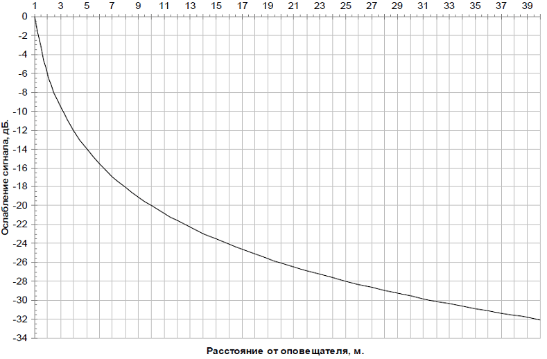
Rice. 1 - Graph of sound pressure attenuation depending on the distance to the sound source F (R) = 20 lg (1 / R)
To simplify the calculations, below is a table of actual values of sound pressure levels from the Mayak-12-3M annunciator at various distances.
Table - Sound pressure generated by a single siren when it is turned on at 12V at a different distance from the siren.
5. Selecting the number of sirens in a particular type of premises
The floor plans show the geometric dimensions and area of each room.
In accordance with the assumption made earlier, we divide them into two types:
- "Room" - area up to 40 sq.m;
- "Corridor" - the length exceeds the width by 2 or more times.
- fire protection -30 dB(A);
- standard -20 dB(A)
- N under. – the height of the siren suspension from the floor;
- 1.5m - level 1.5 meters from the floor, at this level there is a sound plane;
- h1 - excess above the level of 1.5 m to the suspension point;
- W is the width of the room;
- D - the length of the room;
- R is the distance from the annunciator to the “calculated point”;
- L - projection R (distance from the annunciator to the level of 1.5 m on the opposite wall);
- S is the sound area.
- D - the length of the room, in accordance with the plan is 6.055 m;
- W - the width of the room, in accordance with the plan is 2.435 m;
- If the siren will be placed above 2.3 m, then instead of 0.8 m, you need to take the size h1 exceeding the height of the suspension above the level of 1.5 m.
- Pdb - loudspeaker sound pressure, according to those. information to the Mayak-12-3M annunciator is 105 dB;
- F (R) - dependence of sound pressure on distance, equal to -15.8 dB in accordance with Fig. 1 when R=6.22 m.
- D - the length of the corridor, in accordance with the plan is 26.78 m;
- W - the width of the corridor, in accordance with the plan is 2.435 m.
- Pdb - loudspeaker sound pressure, according to those. information to the Mayak-12-3M annunciator is 105 dB;
- F (R) - dependence of sound pressure on distance, equal to -14.8 dB in accordance with Fig. 1 when R=5.5 m.
- N is the permissible sound level of constant noise, for hostels it is 75 dB;
- ZD - sound pressure margin equal to 15 dB.
It is allowed to place one annunciator in a room of the “Room” type.
In a room of the "Corridor" type - several annunciators will be placed, evenly spaced throughout the room.
As a result, the number of annunciators in a particular room is determined.
Selection of a "calculated point" - a point on the sounding plane in a given room, as far as possible from the siren, at which it is necessary to provide a sound level of at least 15 dBA above the permissible sound level of constant noise.
As a result, the length of the straight line connecting the annunciator mounting point with the "calculated point" is determined.
Design point - a point on the sound plane in a given room, as far as possible from the siren, at which it is necessary to provide a sound level of at least 15 dBA above the permissible sound level of constant noise, according to NPB 104-03 p.3.15.
On the basis of SNIP 23-03-2003 paragraph 6 "Norms of Permissible Noise" and the "Table 1" given in the same place, we derive the values of the permissible noise level for a hostel of working specialists equal to 60 dB.
When calculating, the attenuation of the signal when passing through the doors should be taken into account:

Conventions
We accept the following conventions:
5.1 Calculation for room type "Room"
Let's define the "calculated point" - the point that is as far as possible from the annunciator.
For suspension, "smaller" walls are selected, opposing along the length of the room, in accordance with NPB 104-03 in clause 3.17.
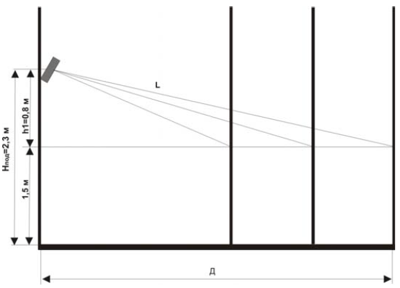
Rice. 2 - Vertical projection of the mounting of the wall annunciator on the airbag
We place the annunciator in the middle of the "Room" - in the center of the short side, as shown in Fig. 3
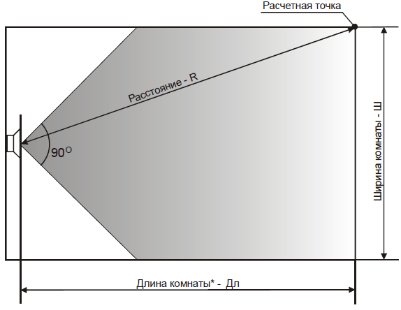
Rice. 3 - Location of the siren in the middle of the "Room"
In order to calculate the size R, it is necessary to apply the Pythagorean theorem:
5.1.1 Determine the sound pressure level at the design point:
P \u003d Rdb + F (R) \u003d 105 + (-15.8) \u003d 89.2 (dB)
5.1.2 Determine the sound pressure value, in accordance with NPB 104-03 p.3.15:
5.1.3 Checking the correctness of the calculation:
P \u003d 89.2\u003e P r.t. \u003d 75 (the condition is met)
SOUE in a protected area.
5.2 Calculation for a room of the "Corridor" type
Annunciators are placed on one wall of the corridor with an interval of 4 widths. The first is placed at a width distance from the entrance. The total number of annunciators is calculated by the formula:
N \u003d 1 + (L - 2 * W) / 3 * W \u003d 1 + (26.78-2 * 2.435) / 3 * 2.435 \u003d 4 (pcs.)
The quantity is rounded up to the nearest whole number. The placement of annunciators is shown in fig. 4.
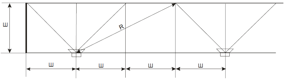
Fig. 4 - Placement of annunciators in a room of the "Corridor" type with a width of less than 3 meters and the distance "to the calculated point"
5.2.1 Determine the calculated points:
"Calculated point" is located on the opposite wall at a distance of two widths from the axis of the annunciator.
5.2.2 Determine the sound pressure level at the design point:
P \u003d Rdb + F (R) \u003d 105 + (-14.8) \u003d 90.2 (dB)
5.2.3 Determine the sound pressure value, in accordance with NPB 104-03 p.3.15:
R.t. \u003d N + ZD \u003d 60 + 15 \u003d 75 (dB)
5.2.4 Checking the correctness of the calculation:
Р=90.2 > Р р.т=75 (condition is met)
Thus, as a result of calculations, the selected type of annunciator "Mayak-12-3M" provides and exceeds the sound pressure value, thereby providing a clear audibility of sound signals SOUE in a protected area.
In accordance with the calculation, we will arrange the sound annunciators, see Fig.5.

Fig. 5 — Plan of placement of annunciators at el. 0.000
In accordance with the regulations that entered into force in 2003. new fire safety standards, the design is required to provide specified sound levels. There is a reference in the document to a method for measuring sound level, but no reference to how to correctly calculate the required number and power of loudspeakers.
Let's try to describe the procedure for calculating the notification in steps.
1. It is necessary to determine the number of speakers to ensure even sound distribution.
- horn..................................................30-45 about
- searchlight ...............................30-45 about
- wall-mounted.................................................75-90 about
- ceiling .................................................80-90 about
Also, according to installation experience, we can assume that it is allowed to place ceiling speakers through a distance equal to the height of the ceiling (in this case, the sound uniformity will turn out to be rather mediocre, but it will satisfy the airbag standards. If uniform sound is required, then you will have to install through "ceiling height - human height "). Wall speakers are installed at a distance equal to the width of the corridor (room). And horn and floodlights are arranged so that crowded places fall into the radiation pattern. When installing wall-mounted and horn loudspeakers, it is necessary to follow the rule that if you want to install several loudspeakers in the same area, it is better to install them in the center and point them in different directions than to put them on the walls and point them towards the center. Legibility and quality in the latter case will be much worse.
2. Determine the noise level in the room. To do this, you can measure it or use a table with approximate levels for various types of rooms.
3. The broadcast level must exceed the noise level by:
- for background music..................................at 5-6dB
- for emergency notification .................... at 7-10dB.
- for high-quality music .............................. at 15-20dB
4. To take into account the attenuation of the sound level from distance (within the radiation pattern), you can use the table:
5. To take into account the increase in sound level depending on the input power, you can use the table:
6. To calculate the sound pressure level at the required distance, you can use the simplified formula:
SPL (dB) = SPL nameplate - SPL attenuation + SPL increase
SPL (db) - level at the required distance in the radiation pattern
SPL passport - sound pressure level according to the passport at a distance of 1 m (dB / W / m)
SPL attenuation - attenuation level depending on the distance (see table)
SPL increase - - level of increase depending on the input power (see table)
From the above formula, you can easily calculate the required power for a single loudspeaker. By summing the power of the speakers, you can calculate the total power of the amplifier. The power of the amplifier is recommended to be selected with a 20% power margin. When operating the system, you will be able to verify this.
For example: there is a retail space measuring 20x30m with a ceiling height of 3m. It is required to sound it with background music, but taking into account the possibility of emergency notification.
For uniform sounding, 20:3-1 = 5 rows of 30:3-1 = 9 pieces will be required. total 45 pcs.
The sound level at a distance of 1.5 m from the loudspeaker (ceiling height - the height of the shortest person) must be at least 63 + 7 = 70 dB. Therefore, if we use loudspeakers ART-01 (Inter-M) with a power of 1 W (according to the passport, the sound pressure level at a distance of 1 m is 90 dB.), The formula will take the form:
SPL (Sound Pressure Level) = 90-3+0 =87 dB. Which is more than 70. So that these speakers are suitable for sounding this room. And in principle, if only an emergency notification is needed, then the number can be even less (you can count it yourself).
If, however, you do not want to bother yourself with "complicated" mathematical calculations, then you can always use any program for calculating the number of loudspeakers, for example, from TOA. When using equipment from other manufacturers, it is necessary to take into account the difference in their sound pressure from the selected type. You can download the program for calculating warning systems (8,2mb)
Hello dear friends! Vladimir Raichev is in touch with you, I have prepared another rather interesting article for you. The fact is that before the installation of the SOUE, an acoustic calculation of the warning system is necessarily made. Did you know about it? About what it is and what it is eaten with, I will try to tell you.
In the construction of many areas of a building, it is extremely important how sound travels through them. Concert halls, theaters are a vivid example of this. The acoustics of these rooms largely determines the attendance, the desire of celebrities to perform there.
The acoustic calculation of such cultural and entertainment facilities is carried out at the design stage, when it is possible to change a lot of building parameters to improve the sound of voices and musical instruments.
It is more difficult if it is necessary to calculate the acoustics of an existing, operated room or building. It is with this that those who design (SOUE) most often have to deal with in case of unforeseen, emergency situations - fires, explosions, man-made disasters.
It should be clarified that all SOUE can be conditionally divided into 2 groups:
- Sound notification is the 1st or 2nd type of systems, where the terminal devices - alarms are sirens and other sources of sharp, loud sound of various tones.
- Speech is 3 (most common) or 4, 5 types. Annunciators are used there - loudspeakers, speakers, horns used for most rooms; sound projectors for large premises; line arrays for broadcasting messages, pre-recorded texts in sports, cultural and entertainment facilities, airports, railway stations.
Usually, the acoustic calculation of CO is carried out when designing new construction projects, equipping already operated buildings with systems of 3–5 types.
This is due to the fact that types 1, 2 are used in small areas, capacity, number of places, construction volume, number of storeys in rooms or buildings where installed sound sirens, tinted signals provide excellent audibility due to loudness, a sharp difference from the level of the usual background noise anywhere in the building.

Noise level in rooms, power of acoustic devices
It should be noted that the background noise level in the premises of the building, on the territory of the enterprise, organization is one of the significant characteristics that determine the acoustic calculation of the warning system, affecting its effective operation.
According to the daily noise level, the premises can be divided into the following types:
- Low noise - offices of administrative, governing bodies, offices, medical institutions.
- With a low noise level - shopping pavilions, shops, buildings of airports and railway stations.
- Noisy. Super- and hypermarkets, sports halls, cultural and entertainment facilities, warehouse complexes using electric forklifts.
- With a high level of background noise. Warehouses with equipment with internal combustion engines, places for loading and unloading operations using lifting equipment, production facilities.
- Very noisy. Railway station platforms, music clubs.
Naturally, the sound pressure of speech warning devices, which determines their loudness, must significantly exceed the noise level, which greatly attenuates the sound of any loudspeaker device similar to it.

This solution is not always possible. In the premises of music clubs, cinema-concert halls, cinemas, where the values of the usual sound level for them are already close to critical for the hearing organs, it is necessary to reduce the volume or completely turn off the broadcast of the music program, the sound of the film before giving an alarm message, or block the SOUE with the sound amplification system culturally - entertainment establishment.
Power, type, method of installation (ceiling, wall, suspended), their number, as well as distance, angle, radius, maximum possible sound area of acoustic devices, their optimal placement in the premises of the building - the main characteristics used, determined during acoustic calculation .
Initial data
First of all, it is the measured on site or pre-calculated, average maximum noise level in the room where the voice alarm devices will be installed. Here are sample values for various objects:
- Hotels, medical, educational, cultural and educational institutions - 55-65 dB.
- Administrative, office premises, trade pavilions, shops, warehouses - 65-70 dB.
- Large shopping centers, restaurants, railway stations, airports - 70-75 dB.
- Production shops of industrial enterprises, concert, sports complexes - 75–80 dB.

In addition, the acoustic calculation will require the following information:
- The geometric dimensions of the room.
- Sound pressure level of selected warning devices.
- Sensitivity, power of annunciators.
- Width of the radiation pattern of each device, which determines the zone of a full-fledged notification.
- Sounding area of the siren (based on the technical data sheet of the product) depending on the noise level.
All these data serve as the basis for the acoustic calculation.
Calculation methods and programs
There are methods, instructions for self-calculation, which outlines a clear sequence for choosing factors, as well as formulas, tables, graphs, diagrams necessary to establish the main parameters of the SOUE for each type of premises, buildings.
In addition, in order to speed up and simplify the process, computer programs have been developed for acoustic calculation of the warning system.

They exist as paid services provided by independent development companies; organizations involved in the design of SOUE, as well as free calculation programs from manufacturers of products-components of warning systems, sound equipment, which can be downloaded from their official websites.
The main parameters successively determined by the acoustic calculation are:
- The maximum sounding distance of the selected siren in the conditions of future operation.
- The maximum sound radius.
- Real beam angle.
- The maximum possible sounding area of the siren.
Then, taking into account the last characteristic on the layout of the room to be equipped with a warning system, all annunciators are placed - loudspeakers, speakers, other acoustic systems used in the SOUE, so that an alarm message about an emergency can be heard anywhere in the room , actions for safe evacuation from the building.
The required number of sound devices for voice announcements, in turn, serves as the basis for calculating the total power of the system, choosing broadcasting amplifiers, switching devices, backup power supplies in case of power outages in the building, and constructing the system of the SOUE as a whole.

Nuances of acoustic calculation
It is not enough to determine the single, total power of the necessary warning devices for a given room or building. There are many subtleties, trifles known to specialists of design and installation organizations, established both theoretically and from the experience of operating voice warning systems that affect its operation:
- The distance between adjacent sirens must not exceed twice the maximum sounding radius for this product model.
- All acoustic devices selected for use in the public address system should not have external sound or power controls.
- In addition to loudness in speech notification, clear audibility, intelligibility and uniformity of information presentation are extremely important. Therefore, you should not try to install one or more very powerful sound speakers, loudspeakers to block the entire area of the room.
- In halls and other large areas, distributed public address systems are required, consisting of a large number of evenly distributed sirens, the sound area of which overlaps each other. This will eliminate both excessive concentration and incorrect distribution of the reflected sound.
- At the same time, in corridors, narrow and long rooms, it is recommended to use sound projectors with sound pressure power adjusted by specialists in order to select the optimal perception at each point. This will make it possible to significantly reduce the number of annunciators in buildings of the corridor type, the required power of amplifiers for broadcasting messages, and as a result, reduce the cost of the system.

Why it is necessary to entrust acoustic calculation to professionals
But this is just the tip of the iceberg. Without doubting the knowledge and competence of technical specialists of enterprises and organizations, they should be warned against independently conducting acoustic calculations if it will serve as the basis for installing a voice warning system. There are several reasons for this:
- For the installation of SOUE, an integral part of which is a sound, speech warning system, in existing, operated buildings, a license from the Ministry of Emergency Situations for this type of work is required.
- At the same time, it is paradoxical, but it is possible to design SOUE in such buildings without any permits. However, in practice, the working draft of the SOUE is usually developed by an organization that subsequently performs installation and commissioning, signs an act of work performed, including in the territorial agency of the Ministry of Emergency Situations (as far as my memory serves me, this process is voluntary), and accordingly, bears full responsibility in accordance with the legislation.
- For newly built facilities for the design and installation of the SOUE, SRO permits for a legal entity are required.
In addition, it is quite difficult to reconcile the calculated acoustic values with the technical, electrical parameters, characteristics of power amplifiers, switching devices, uninterruptible power supplies, backup power supplies, without special techniques, so that the system is stable, and voice messages, musical broadcasts are clearly audible in any the premises of the building protected by the SOUE.

Therefore, for design, installation and commissioning, it is better, more expedient to involve specialists from enterprises, organizations that have the appropriate permits, long experience in the field of industrial safety.
It will be useful to learn about the objects where they designed and installed the voice warning system in order to independently verify its effectiveness. Feedback from the owners of the building, tenants of the premises will also be useful.
They are the most important component of fire protection systems. In the process of designing warning systems, an electro-acoustic calculation is performed. The basis for electroacoustic calculation is a set of rules developed in accordance with Article 84 of the Federal Law FZ-123 SP 3.13130.2009 of July 22, 2008. This article is based on the following main points of the set of rules.
- 4.1. The sound signals of the SOUE should provide a total sound level (the sound level of constant noise together with all the signals produced by the annunciators) of at least 75 dBA at a distance of 3 m from the annunciator, but not more than 120 dBA at any point of the protected premises
- 4.2. Sound signals of the SOUE should provide a sound level of at least 15 dBA above the permissible sound level of constant noise in the protected room. Sound level measurement should be carried out at a distance of 1.5 m from the floor level
- 4.7. Installation of loudspeakers and other voice annunciators in the protected premises should exclude the concentration and uneven distribution of the reflected sound
- 4.8. The number of sound and speech fire alarms, their placement and power must ensure the sound level in all places of permanent or temporary stay of people in accordance with the norms of this set of rules
The meaning of electroacoustic calculation is reduced to determining the sound pressure level at the calculated points - in places of permanent or temporary (probable) stay of people and comparing this level with the recommended (normative) values.
In the sounded room there is a different kind of noise. Depending on the purpose and features of the room, as well as the time of day, the noise level varies. The most important parameter in the calculation is the value of the average noise. Noise can be measured, but it is more correct and convenient to take it from ready-made noise tables:
Table 1In order to hear sound or speech information, it must be 3 dB louder than the noise, i.e. 2 times. The value 2 is called the sound pressure margin. In real conditions, the noise changes, therefore, for a clear perception of useful information against the background of noise, the pressure margin should be at least 4 times - 6 dB, according to the standards - 15 dB.
Satisfaction of the conditions set forth in clauses 4.6, 4.7 of the set of rules is achieved by organizational measures - the correct placement of loudspeakers, preliminary calculation:
- loudspeaker sound pressure,
- sound pressure at the calculated point,
- effective area sounded by one loudspeaker,
- the total number of loudspeakers needed to sound a certain area.
The criterion for the correctness of the electroacoustic calculation is the fulfillment of the following conditions:
- The sound pressure of the selected loudspeaker must be "at least 75 dBA at a distance of 3 m from the siren", which corresponds to a loudspeaker sound pressure value of at least 85 dB.
- Sound pressure at the design point d.b. above the average noise level in the room by 15dB.
- For ceiling speakers, the installation height (ceiling height) must be taken into account.
If all 3 conditions are met, the electroacoustic calculation is completed, if not, then the following options are possible:
- choose a loudspeaker with greater sensitivity (sound pressure, dB),
- choose a loudspeaker with more power (W),
- increase the number of speakers
- change the speaker layout.
2. Input parameters for calculation
The input parameters for calculations are taken from the terms of reference (TOR) (provided by the customer) and technical specifications for the equipment being designed. The list and number of parameters may vary depending on the situation. Sample input data is shown below.
Speaker options:
- SPL
- Pgr– loudspeaker power, W,
- SDN– Beam width, deg.
Room options:
- N– Noise level in the room, dB,
- H– Ceiling height, m,
- a– Room length, m,
- b– Room width, m,
- Sp– Room area, m2.
Additional data:
- ZD– Sound pressure margin, dB
- r– Distance from loudspeaker to calculated point.
Sounded room area:
Sp \u003d a * b
3. Loudspeaker sound pressure calculation
Knowing the rated power of the loudspeaker (PW) and its sensitivity SPL (SPL from the English Sound Pressure Level - the sound pressure level of the loudspeaker measured at a power of 1W, at a distance of 1m), it is possible to calculate the sound pressure of the loudspeaker developed at a distance of 1m from the emitter.
| Rdb = SPL + 10lg(Pvt) | (1) |
- SPL– loudspeaker sensitivity, dB,
- rvt- loudspeaker power, W.
The second term in (1) is called the "power doubling" rule or the "three decibel" rule. The physical interpretation of this rule is that for each doubling of the source power, its sound pressure level increases by 3dB. This dependence can be represented tabularly and graphically (see Fig. 1).
Fig.1. Sound pressure versus power
4. Calculation of sound pressure
To calculate the sound pressure at the critical (calculated) point, it is necessary:
- Select calculated point
- Estimate the distance from the loudspeaker to the calculated point
- Calculate the sound pressure level at the calculated point
As a calculated point, we choose the place of possible (probable) location of people, the most critical in terms of position or distance. The distance from the loudspeaker to the calculated point (r) can be calculated or measured with an instrument (range finder).
Calculate the dependence of sound pressure on distance:
| P20 \u003d 20lg (r-1) | (2) |
- r– distance from the loudspeaker to the calculated point, m;
- 1
ATTENTION: formula (2) is valid for r > 1.
Dependence (2) is called the "inverse square" rule or the "six decibel" rule. The physical interpretation of this rule is that for each doubling of the distance from the source, the sound level decreases by 6dB. This dependence can be represented tabularly and graphically, Fig. 2:

Fig.2. Sound pressure versus distance
Sound pressure level at the design point:
- N- Noise level in the room, dB (N from English Noise - noise),
- ZD– Sound pressure margin, dB.
At AP=15dB:
| P > N + 15 | (5) |
If the sound pressure at the calculated point is higher than the average noise level in the room by 15 dB, the calculation is correct.
5. Effective range calculation
The effective sound range (L) is the distance from the sound source (loudspeaker) to the geometric location of the calculated points located within the limits of the SRP, the sound pressure in which remains within (N + 15dB). In technical slang, "the distance that the loudspeaker penetrates."
In English literature, the effective acoustical distance (EAD) is the distance at which speech clarity and intelligibility is maintained (1).
Calculate the difference between the sound pressure of the loudspeaker, the noise level and the pressure margin.
- p- the difference between the sound pressure of the loudspeaker, the noise level and the pressure margin, dB.
- 1 - coefficient taking into account that the sensitivity of the loudspeaker is measured at 1 m.
6. Calculation of the area sounded by one loudspeaker
The basis for estimating the size of the sounded area is the following setting:
The calculation will be carried out on the basis of the following assumptions: The radiation pattern (radiation) of the loudspeaker can be represented as a cone (sound field concentrated in a cone) with a solid angle at the top of the cone equal to the width of the radiation pattern.
The area sounded by the loudspeaker is the projection of the sound field limited by the opening angle onto a plane drawn parallel to the floor at a height of 1.5 m. By analogy with the effective range: The effective area sounded by the loudspeaker is the sound pressure area within which does not exceed the value of N + 15dB (form 5).
NOTE: The loudspeaker radiates in all directions, but we will rely on input data - sound pressure levels within the radiation pattern. The correctness of this approach is confirmed by statistical theory.
Let's break the loudspeakers into 3 classes (types):
- ceiling,
- wall,
- horn.
8. Calculation of the effective area sounded by the wall loudspeaker
9. Calculation of the effective area sounded by a horn loudspeaker
10. Calculation of the number of loudspeakers required to sound a certain area
Having calculated the effective area sounded by one loudspeaker, knowing the total dimensions of the sounded territory, we calculate the total number of loudspeakers:
| K \u003d int (Sp / Sgr) | (16) |
- Sp– sounded area, m2,
- Sgr– effective area sounded by one loudspeaker, m2,
- int is the result of rounding to an integer value.
11. Electro-acoustic calculator
The overall result obtained in the form of a flowchart:
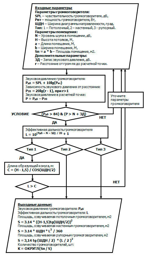
Fig.6. Block diagram of an electroacoustic calculator
Programming example
This calculator (written in Microsoft Excel) implements an elementary short method - the electroacoustic calculation algorithm described above. This program can be downloaded from our website.
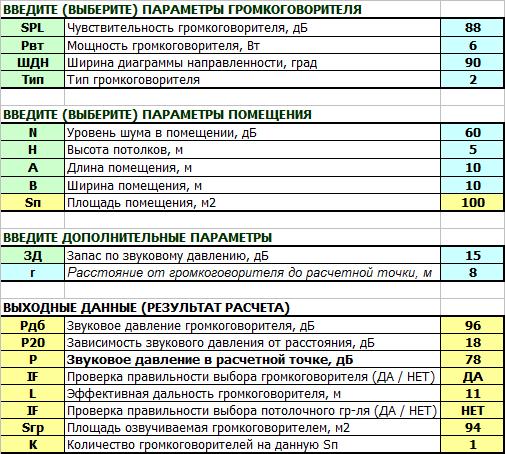
Fig.7. Electroacoustic Calculator in Microsoft Excel
Based on the developed calculation algorithm, the ON-LINE electro-acoustic calculator on our website also works.
APPENDIX 1. List and brief characteristics of ROXTON loudspeakers
| Loudspeaker ROXTON | SPL, dB | R W, W | SDN, gr. | R db, dB |
|---|---|---|---|---|
| Ceiling speakers | ||||
| PA-03T - Ceiling Loudspeaker | 88 | 3 | 90 | 93 |
| PC-06T - Ceiling Loudspeaker | 90 | 6 | 90 | 100 |
| PA-610T - Ceiling Loudspeaker | 88 | 6 | 90 | 96 |
| PA-620T - Ceiling Loudspeaker | 90 | 6 | 90 | 96 |
| PA-20T - Ceiling Loudspeaker | 92 | 20 | 90 | 101 |
| WP-10T - Ceiling Loudspeaker | 92 | 10 | 90 | 98 |
| PA-30T - Ceiling Two Way Loudspeaker | 90 | 30 | 90 | 104 |
| T-200 - Hanging Loudspeaker | 92 | 10 | 90 | 102 |
| SP-20T - Pendant Loudspeaker | 92 | 10 | 90 | 104 |
| Wall speakers | ||||
| WP-03T - Wall Mounted Speaker | 86 | 2 | 90 | 91 |
| WP-06T - Wall Mounted Speaker | 90 | 6 | 90 | 96 |
|
4.2. Sound signals of the SOUE should provide a sound level of at least 15 dBA above the permissible sound level of constant noise in the protected room. Sound level measurement should be carried out at a distance of 1.5 m from the floor level. 4.3. In sleeping rooms, sound signals of the SOUE should have a sound level of at least 15 dBA higher than the sound level of constant noise in the protected room, but not less than 70 dBA. Measurements should be taken at the level of the sleeping person's head. 4.4. Wall-mounted sound and voice annunciators should be located in such a way that their upper part is at least 2.3 m from the floor level, but the distance from the ceiling to the top of the annunciator must be at least 150 mm. 4.5. In protected premises where people are wearing noise-protective equipment, as well as in protected premises with a noise level of more than 95 dBA, sound annunciators must be combined with light annunciators. The use of light flashing annunciators is allowed. 4.6. Voice annunciators must reproduce normally audible frequencies in the range from 200 to 5000 Hz. The sound level of information from voice alarms must comply with the standards of this set of rules in relation to sound fire alarms. 4.7. The installation of loudspeakers and other voice annunciators in the protected premises should exclude the concentration and uneven distribution of the reflected sound. 4.8. The number of sound and speech fire alarms, their arrangement and power must ensure the sound level in all places of permanent or temporary stay of people in accordance with the norms of this set of rules. | ||||