Ventilation in the bathroom projects for autocad. Ventilation systems
To create healthy and comfortable microclimatic conditions in the room, high-quality air exchange is necessary. Exhaust air saturated with carbon dioxide, excess moisture, dust and various contaminants must be removed in a timely manner, and its place must be taken by fresh air masses saturated with oxygen. Such circulation is dictated by common sense and regulated by construction and sanitary and epidemiological standards.
As you know, planning any engineering networks in a house begins with the preparation of project documentation and calculations. Competent allows you to create in each room of the building the microclimate necessary for normal human life.
Norms and rules used in the design of engineering networks
is the creation of a technically and economically justified layout of ventilation ducts and a competent selection of equipment that will ensure the microclimate standards regulated by 2.09.04-87. In addition, a competent project provides for 100% operability and maintainability of the system, as well as satisfaction of all architectural and technical requirements.Must comply with strictly defined sanitary norms and state standards.
When designing ventilation, SNiP 2.04.05-91 is the main document that any designer is guided by.
In addition to this set of rules, the following regulatory documents may also become necessary:
- SNiP 2.01.02-85;
- SNiP II-12-77;
- GOST 12.1.005-88;
- SNiP 2.08.01-89;
- SNiP 2.08.02-89;
- SNiP 2.09.04-87;
- SNiP 2.09.02-85;
- SNiP 2.01.01-82.
Project development stages

At the first stage of the development of the ventilation system project, the customer meets the designer, where the terms of reference are drawn up and the initial data necessary for correct calculations are determined.
The second stage is the provision to the customer of technically and economically justified schemes of ventilation systems, with options for the equipment used for this. From the presented options, the customer chooses the best one and makes his comments, after which he submits it for approval to the appropriate authorities. Only after the comments from the regulatory authorities have been eliminated, the project proceeds to the third phase - the preparation of complete technical documentation with the specifications of the necessary materials and equipment, as well as an estimate of the work.
The project can be created "the old fashioned way", on a drawing board, but, as a rule, modern companies involved in design work use software for this.
Programs for the design of ventilation systems
Today, there is a mass of software that serves to significantly speed up the process of performing calculations, drawing up duct layouts, filling out specifications and drawing up drawings. Despite the apparent simplicity, the designer must have the appropriate knowledge, experience in dealing with software, etc. Let's consider several common programs that help ventilation system designers in compiling project documentation.
Autocad
The program is designed to create the most accurate drawings, diagrams and other design documentation in two-dimensional or three-dimensional display. AutoCAD has two types of interface:

When designing ventilation in autocad, the designer will have access to: a full set of functionality for drawing up and checking drawings, the ability to scale, and the use of panoramic functions. In addition, it is possible to use and link objects from third-party libraries, import-export tables and text files, layers, publish 3D drawings, and much more.
Today, AutoCad is the software that is most common in architectural design and design offices, since it is this utility that has the function of supporting team work on a project.
It should be understood that the AutoCad program is not just an electronic drawing board, it is a powerful software package that requires certain knowledge and experience to use.
- First of all, you should make sure that your PC has the system requirements to work with this utility (more than 2 GB of RAM; 2 GB of free disk space; high resolution monitor).
- After installing the software, familiarize yourself with the interface, which consists of a quick access panel (next to the red letter A in the upper left corner); ribbon, which, in turn, consists of several bookmarks; the status bar (at the bottom of the screen) and the command bar (above the status bar).
- To create a new document, select File - New.
Next, you can create a sketch, drawing, or complex object. Basic knowledge of English is required for work, since the interface language is English. In addition, you need to be at least an engineer and know the commands that will be needed to create drawings. To learn how to use this utility, you can use the reference book directly from the program menu.
AutoCad is a paid program with a free 30 day trial period. The cost of the latest licensed network version of AutoCad 2016, on the developer's website, is 5 thousand euros. There are special prices for local and network versions of the program for educational institutions.
magicad
This powerful utility is designed to perform calculations and three-dimensional design of engineering networks. The magicad ventilation design program includes several basic modules, among which is the Magicad-Ventilation block. 
As a graphical platform, the utility uses AutoCad or RevitMap. This software package allows you to:
- Creation of ventilation schemes with tracing both in manual and automatic mode.
- Arrangement of fittings and other equipment.
- Selection of sections of mines, channels and air ducts.
- Calculation of aerodynamic resistance of air ducts and equipment.
- Acoustic calculation.
- Balancing the ventilation system in automatic mode.
Magicad has the following features:
- Use of ventilation equipment base.
- Work with text designations of elements.
- Creation of specifications of materials and equipment;
- Control over intersecting elements in sketches and drawings.
- Work in 2D and 3D modes.
- Export data to other programs and much more.
A feature of this program is the presence of a database of ventilation equipment, which contains a huge number of products, with complete data on the pressure, air flow, dimensions, and geometry of the element, as well as its noise characteristics, etc. When drawing up a drawing, the program will automatically select shaped products, with connecting two air ducts - a tee or a cross, if the diameter of the air duct changes, the Magicad utility will immediately suggest the necessary adapter.
The Magicad program allows the designer to create projects of ventilation systems of any complexity in the shortest possible time.
The interface language is English and Russian. The cost of the full local licensed version is 4560 euros. The price of a full network license is 5700 euros. There are special offers for purchasing upgrades for 1, 2 and 3 years.
To successfully work with Magicad Ventilation, you need to be an engineer, be able to work with the AutoCad graphics platform. Official representatives of the developer often conduct online training on how to work in the program. The average cost of such training is from 10 to 16 thousand rubles. for the course.
Ventcalc
The program among designers is considered the most simple and functional. Indeed, to create a ventilation network diagram, it is enough to enter the required initial data and the program will provide a ready-made sketch with all the necessary data for further selection of equipment. 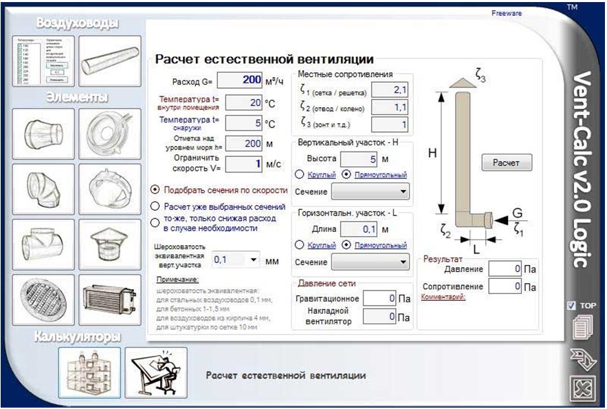
Regardless of the chosen type of ventilation system, this utility copes equally well with the necessary calculations. The functionality of the program allows you to:
- Make a calculation of the cross section of the air outlets, taking into account all variables.
- Calculation of the resistance of mines and channels. Based on the calculations, the program automatically selects ventilation equipment.
- Calculation of the aerodynamic resistance of the network.
- Make a competent calculation of natural ventilation.
- Determine the optimal section of the ventilation shaft, which will ensure the predominance of thrust over the resistance of the air mixture at a certain flow rate.
- Make a calculation of the heating power of the heater.
Vent calc will perform the necessary calculations in the shortest possible time, which will greatly simplify the work of the designer. The advantage of this software is that since 2010 Vent calc has been distributed free of charge. The software interface language is multilingual.
Сadvent
The cadvent ventilation design software is a kind of add-on for drawing ventilation systems, created on the Avtocad graphics platform. This utility contains a complete set of tools for drawing diagrams, has powerful capabilities for conducting the necessary calculations, creating three-dimensional models, presentations, etc. 
This software product allows you to:
- Calculate cross-sections and pressure losses in air ducts.
- Acoustic calculations.
- Create two-dimensional drawings with the necessary notation.
- Produce 3D modeling.
- Prepare specifications for the necessary elements of the system, with possible export to Excel.
- Create high quality 3D presentations.
The main feature of this software is the ability to create complete sets of working documents, including calculations, specifications of materials, two - and three-dimensional drawings, individual sections and elements of the system.
To work in this software, you must be able to handle the avtocad graphics platform, be able to work with spreadsheets and libraries. The interface language is English. The cost of the software package depends on its configuration: ventilation module with the ability to manually update databases - 500 USD; ventilation module with automatic database update - 1500 USD; ventilation, heating, plumbing module with a complete base of elements from European manufacturers - 2500 USD
Despite the apparent simplicity of creating projects in the software presented above, this is a rather technically complex process that requires extensive knowledge, therefore, to create project documentation and calculations, contact only specialists.
To ensure normal air exchange in a house or apartment, two components are necessary: the inflow of fresh air through the living rooms and its outflow from the technical ones. Ventilation in the bathroom and toilet is one of the components of the outflow. Therefore, it is necessary to do it right.
According to the principle of operation, ventilation can be natural or mechanical, they also say - forced. The natural movement of air occurs due to the movement of wind, temperature differences and, resulting from this, pressure drops. When mechanical ventilation is used, air movement is caused by fans.
From the point of view of an urban man, forced movement is preferable: everyone has long been accustomed to the fact that life support depends on the availability of electricity. And it rarely disappears in cities. But in rural areas in winter, power outages are rather the norm. Therefore, probably, they tend to mainly make systems non-volatile, or at least redundant.
But the natural ventilation in the bathroom and bathroom should be too large. After all, the lower the speed of air movement through the channel, the greater the cross section of the duct is needed to ensure the transfer of the required volumes. No one will argue that when the fan is on, the air moves faster. This is even reflected in the SNiP: the rate of movement for ventilation systems with natural circulation is up to 1 m 3 / h, for mechanical ones - from 3 to 5 m 3 / h. Therefore, for the same room and conditions, the dimensions of the channels will be different. For example, to transfer a flow of 300 m 3 / h, you will need:

Therefore, few people today manage with natural ventilation. Unless in small houses (up to 100 sq. m.). Even in apartments with channels leading to the roof, bathrooms and toilets are ventilated using fans.
Organization rules
When installing an air movement system, you need to remember the basic principle: in order for everything to work efficiently, it is necessary to ensure the flow of air through the living rooms and its flow into the technical rooms. From there, he leaves through the ventilation ducts.
Today, air flow has become a problem: by reducing heating costs, we have cut off almost all sources of its supply. We install airtight windows, we insulate the walls through which at least a little air enters with airtight materials. The third source - entrance doors - today, almost all have iron ones, with a rubber seal. There was, in fact, the only way - airing. But we do not abuse it at all: it blows out heat. As a result, to the problems of lack of oxygen in the room, the problem of dampness is added: there is no inflow, and the outflow is inefficient. Even forced.

If you want the ventilation to be normal, and the walls in the rooms not to “wet”, make ventilation holes. There is such an option on metal-plastic windows, and there are separate devices that are mounted anywhere on the wall. They are available with adjustable shutters, of various shapes and sizes, and are covered with bars from the outside. It is best to install under the windows, above or behind the batteries. Then they are not visible in the room, and in winter the air coming from the street is heated.
Having ensured the inflow, care must be taken to ensure that it enters the technical premises through the doors. Therefore, there should be gaps under all doors: through them, air will flow into other rooms. It is advisable to install a ventilation grill in the bathroom doors and / or also make a gap of at least 2 cm from the floor. The same rules apply to other technical rooms: kitchen and toilet. Only if there is movement of air masses will ventilation work.

The doors of technical rooms - kitchens, bathrooms, toilets - must have ventilation grilles or valves. There are even valves with noise absorption, and the smell, if properly organized, will never get into other rooms
Calculation of fan performance for bathroom and toilet
To decide which fan to put on the bathtub with a toilet, you need to calculate the necessary air exchange. The calculation is a whole system, but when installing a fan, the main attention is paid to its characteristics: it provides the required air speed. In order not to interfere in the calculations, its performance can be taken according to average numbers.

Air exchange rate for different rooms. With their help, ventilation is calculated in the bathroom and toilet
As you can see from the table (this is from SNiP), for a bathroom, at least 25 m 3 / h should be “pumped” per hour, for a toilet or a combined bathroom, the speed should be twice as high - 50 m 3 / h. These are the minimum values. In reality, through three (or two) technical rooms - a kitchen, a toilet, a bathroom - as much air should leave as it enters through the supply ventilation.
The calculation of the inflow is carried out according to the volume of all residential premises and usually exceeds it by 1.5-2 times, and the minimum values \u200b\u200bindicated in the table are not enough to ensure the required air exchange. Therefore, the performance of the fans is taken with at least a double margin, and even more for kitchens: this way there will be no unpleasant odors in the apartment, as well as dampness and fungi. Therefore, when going to the bathroom with a fan with a lower capacity than 100 m 3 / h, it is better not to take it.
Choice
First of all, you need to decide where you will put the fan: in the duct or on the wall. Accordingly, the type: channel or wall. In wall-mounted versions, there can also be two types: for installation at the inlet of the ventilation duct - they create more pressure, and for ductless installation - exit directly through the wall to the street. For a channelless installation, axial-type fans are usually used - they cannot create a pressure of more than 50 Pa; for this reason, they are not installed in channels.

In addition to the performance that you calculated, another important characteristic is the noise level. The smaller it is, the better. It is good if the noise level is no more than 35 dB.
Another thing to pay attention to is the level of electrical safety. For use in rooms with high humidity, a protection level of at least IP 44 is required (indicated on the fan housing).

Connecting a fan in the bathroom
For the fan to work, power is needed and the main question is how to connect it. There are several possibilities:
- Connect in parallel with lighting. When you turn on the light in the bathroom or toilet, the fan automatically starts. But it also turns off automatically when the light is turned off. For the toilet, this situation is normal, but for the bathroom - not always. For example, after taking a hot shower, all the steam will not go away. Therefore, for bathrooms, you can use a different way to connect the fan or set a shutdown delay (a special device on which you can set the time interval after which the power will turn off).
- Output to a separate switch key or put a separate toggle switch / button.
- Set a timer that will automatically power up according to a schedule.
The electrical part is the hardest part. You will have to punch a strobe in the wall, “pack” the power cable into it, bring it to the installation site of the switch and connect it there, depending on the chosen method.
Checking the ventilation duct
Installing a fan in the bathroom with your own hands begins after checking the condition of the channel. To do this, remove the grate, if it has not been dismantled yet, and bring a flame (candle, lighter) or a piece of paper to the hole. If the flame or leaf is pulled steadily towards the channel, the draft is normal. If it stretches, then bends back - the thrust is unstable. In this case, if you live in an apartment building, smells from neighbors upstairs or downstairs can get to you. Then the smell in the toilet from the ventilation is possible. Traction needs to be stabilized.
If the flame or leaf almost does not deviate, the channel is clogged or blocked. In this case, mold and dampness, as well as unpleasant odors are guaranteed throughout the apartment, and in the bathroom, so be sure.

In case of abnormal draft, residents of high-rise buildings clean the channels themselves or call maintenance services. In private homes, in any case, everything falls on the shoulders of the owners. If the channel is unstable, you may have taken it out without taking into account the wind rose and the thrust periodically overturns. You can solve the problem by moving the exit, but it's not easy. To begin with, you can try to put a deflector (if it is not there) or slightly increase / decrease the height.
Features of forced ventilation in the bathroom
When the fan is installed while it is running, the amount of air discharged increases significantly. But due to the fact that the case covers part of the channel section, at other times, when the fan is not working, the flow decreases three times. As a result, the overall performance of the ventilation system drops.
To prevent this from happening, you can install a fan with an air intake grille located below and thus increase the performance to normal. The second option is to leave a gap of 1.5-2 cm between the case and the wall during installation, i.e. make legs. Air will enter the slot and ventilation will be normal in any case. See the video for more on this.
Having chosen the installation method and the type of grille, you can proceed directly to the installation. Fan sizes may vary. Therefore, each case is individual. But the basic steps are standard:
- A hole must be made on the tile under the body. The easiest way is to attach a fan and outline. Then, with a special nozzle on a drill or a grinder, cut a hole of the appropriate size.
- Remove the front panel from the fan. It is attached with one bolt at the bottom. The bolt was unscrewed, the grille was removed. Holes for fasteners are now visible. We insert the fan in this form into place (into the channel), mark on the tile with a pencil or marker the place where the bolts will be.
- With a drill of the appropriate diameter, we make holes in the tile and wall to fit the size of the dowel.
- We make an incision in the tile, where we will pass the power wire.
- We insert dowels.
- We stretch electrical wires through a special hole on the fan housing (if there is no hole, it is drilled).
- We install in place, tighten the bolts.
- We connect the wires.
- We check the performance and install the grate.
- For wooden toilets, all this is only partly true. Read about
Ventilation in the bathroom in a private house
Here the main difficulties may arise in the construction of exhaust channels. When planning, they can be brought together in one place and then brought to the roof. This is more difficult in terms of internal wiring - you will have to pull the ducts to the right place, and also more expensive during construction. But the look is solid.

Another way to arrange ventilation ducts: bring it through the wall, and then lift it up along the outer wall. According to the rules, for normal draft with natural ventilation, they should rise 50 cm above the ridge. But one common duct will be brought out by you or a separate one for each room - it depends on your desire or on the layout. The picture will look something like this.

There is another option: to make a mechanical hood that will work exclusively from the fan. Then, depending on the layout, one of the two options presented in the photo is suitable.

In the first case (on the left), the exhaust hole is made right in the upper part of the wall (in order for air exchange to be effective, it must be located opposite the door, obliquely, at the top). With this device, a conventional wall fan is used. The same figure shows how the number of required channels can be reduced. If your bathroom and toilet rooms are nearby, through a thin partition, then you can make a hole in the partition and install a grate. In this case, the ventilation of the bath will go through the toilet.
In the second option (pictured on the right), an air duct with a duct fan is used. The solution is simple, only there is one caveat: if the air duct ends under the roof overhang (it is short in the photo, but there are also long ones), then the tree will turn black after a while. If you draw a conclusion from the toilet this way, this may not happen, and in the case of the bathroom, high humidity will make itself felt in a couple of years. In this case, you can “pull out” the air duct to the roof cut or bring it up through the knee (but raise it 50 cm above the roof).
Such work, of course, is a very important point in the construction process, which includes the selection of the necessary equipment, as well as determining the design and parameters of ventilation units. Such complex engineering work must be carried out by professional specialists who have the necessary software.
You can calculate ventilation in a regular Excel.
The Vent-Calc program is designed for calculation and design of ventilation systems. This software allows you to select the air duct in accordance with the specified conditions (temperature, flow and allowable air speed). The basis of Vent-Calc is the method of hydraulic calculation of air ducts using the Altshul formulas:
- Hydraulic calculation of the duct.
- In accordance with the formulas VSN 353-86 - calculation and selection of elements of the ventilation system (bends, branches, narrowing and expansion of the channel).
- Calculation of the natural ventilation system, that is, the selection of sections of the ventilation duct in such a way that the draft in the duct is higher than the resistance at the specified air flow.
- Calculation of the thermal power of the air heater (air heater).
Due to the fact that the program works with the results of formulas, and not fixed calculated values \u200b\u200band tables, the results obtained can sometimes differ slightly from the tabular ones.
Working window of the Vent-Calc program
CADvent program
CADvent is a ventilation calculation program based on AutoCAD with a complete set of tools for drawing, modeling and presenting HVAC systems. It belongs to the category of engineering tools for professional designers who develop ventilation, heating and air conditioning systems.
This software allows:
- Easily and quickly create projects in 3D and 2D graphics.
- Improve project visualization performance by quickly responding to various errors.
- Correct the technical data of products used in the project.
- Calculate air, pressure, leaks and noise.
- Use visualization and presentation tools that help to present the project in the most realistic way.
- Use calculations of noise characteristics and pressure levels, which are displayed in reports that are easily exported to an Excel file.
When planning the design and renovation of the bathroom, one small but very important point should be taken into account - the problem of air exchange. Good ventilation in the bathroom and toilet is necessary not only to ensure the flow of fresh air.
With the help of this system, unpleasant odors and excess moisture are removed from the bathroom. If the ventilation system is planned and implemented correctly, bathroom owners will not have to worry about mold and mildew.
The absence of normal ventilation and the excess humidity caused by this circumstance will create almost luxurious conditions for the development of harmful flora.
The building guides clearly indicate the norms that must be followed for effective ventilation of sanitary rooms with high humidity.
The system must supply fresh air to the bathroom or toilet at a rate of 25 cu. m / h, and for a combined unit twice as high - 50 cubic meters. m/hour. These standards are minimum.
Depending on the characteristics of air exchange, natural and forced ventilation are distinguished. In the first case, air exchange occurs due to the difference in air pressure outside and inside the room.
Air streams penetrate through windows, doors, special ventilators, etc. It should be noted right away that due to the peculiarities of the bathroom design, the use of natural ventilation does not always allow you to get the desired effect.
For ductless ventilation in the bathroom, it is necessary to make an opening that will connect the house ventilation duct with the bathroom
With forced or artificial ventilation of the room, special fans are used that provide sufficient air exchange.
Most often, the fan helps to move air from the room to the street, while fresh air masses enter the bathroom from the living quarters.
Sometimes a small fan is placed in the toilet, even with good natural ventilation, to speed up the purification of air from unpleasant odors.
If it is not possible to organize a sufficiently intensive air exchange in a natural way, forced ventilation is carried out without fail.
Depending on the purpose, there are:
- exhaust;
- supply;
- mixed ventilation.
The exhaust principle has already been described a little above: the air is removed through the ventilation duct, and the new one comes from outside. Supply ventilation is organized differently: air is forced in from the outside and forced out through the channel.
When using mixed ventilation, both the air supply and its removal are regulated.

A beautiful decorative grate for the hood in the bathroom will not only hide the design, but can also become a spectacular detail of a stylish interior.
Specialists also distinguish between channel and channelless ventilation, which is characterized by the presence or absence of a ventilation channel.
If possible, the creation of special channels should be avoided. Usually, an opening is made in the wall that opens into the common ventilation duct of a multi-storey building, and a fan is installed in it.
In a separate bathroom, if there is only one room with access to the ventilation duct, another fan is installed in the wall opening between the bathroom and the toilet.
The installation of a separate ventilation duct makes sense in places that require intensive removal of polluted or moisture-saturated air.
Diagnosis of ventilation status
Before you start altering the ventilation in the toilet and bathroom, you should carefully examine its device and check the condition. To begin with, the draft is examined: a sheet of paper, a lit match or a lighter are brought to the vent.
If the paper sticks to the hole, or if the flame is clearly moving towards the ventilation duct, there is a draft. On a hot windless day, the thrust can be significantly less than in other periods.
The presence of draft in itself does not always indicate the normal state of the ventilation system.
It is imperative to check the condition of the ventilation duct, which may be partially cluttered after inept repair work or for some other reason.
By removing obstacles, you can significantly improve the quality of the ventilation system.

To check the draft in the bathroom, a sheet of paper or a lighter flame is brought to the vent. The test should be carried out with the door open and then with the door closed.
If in the latter case the draft has noticeably decreased, you should think about additional means of micro-ventilation.
Most often, it is enough to install special grilles in the doors of the bathroom and toilet to ensure the normal flow of fresh air into these rooms even with the doors and windows closed.
What you need to know about fans
When buying a fan, be sure to evaluate the amount of noise that it produces. The indicator should not exceed 35 dB. In the bathroom, such equipment should completely update the composition of the air about 5-8 times within one hour.

Exhaust fans designed for use in bathrooms can be of different designs and designs, in addition, they vary in power
According to the type of installation, domestic duct fans are distinguished, designed for installation directly in the ventilation duct, as well as radial models.
They are installed at the outlet of the ventilation duct. Usually channel models look unpresentable because they are hidden inside the channel, but radial devices are provided with a beautiful case so as not to spoil the overall impression of the environment.
The design of fans can also vary significantly:
- traditional axial models move air along the axis of the device using special blades and are designed for ductless systems;
- in low-performance diametrical models, a drum-type wheel is used;
- centrifugal devices with a spiral housing are characterized by high performance and increased noise during operation;
- small centrifugal-axial devices are less noisy, but work almost as efficiently as centrifugal models.
Taking into account the specifics of bathroom ventilation, fans are sometimes additionally equipped with timers that allow you to extend the operation of the device in the toilet or gyrostats to more effectively remove excess moisture from the bathroom.
Fans that are weak in power will not be able to provide normal ventilation of the room, however, you should not use too powerful models.
A strong centrifugal fan can cause such an intense air flow that the inflow will not come from outside, but from other vents, and the exhaust air will again be in the house.
Interesting information about installing an exhaust fan in the bathroom is presented in the following video:
Features of ventilation installation
If for some reason there is no ventilation in the bathroom, it is not so difficult to create the necessary system.
Apartment buildings are usually designed in such a way that the ventilation duct is located directly behind the wall of the bathroom or toilet. It remains only to carefully make a hole in the right place (if there is none) so that it goes into this channel.
A radial axial fan is installed inside the opening. The device is connected to the power supply, observing all the requirements for the operation of electrical appliances in rooms with high humidity.
If necessary, mount additional controls (timer, gyroscope, etc.). The niche is closed with a beautiful decorative lattice.
If the apartment has a separate bathroom, and the ventilation duct is located outside the walls of both rooms, the second fan is installed in the same way as described above.
Otherwise, a vent is made in the wall separating the toilet and bathroom. A fan is also placed in this opening and covered with decorative screens on both sides.
Sometimes it is more convenient to use decorative grilles, in which the design provides for mounting the fan in special sockets.
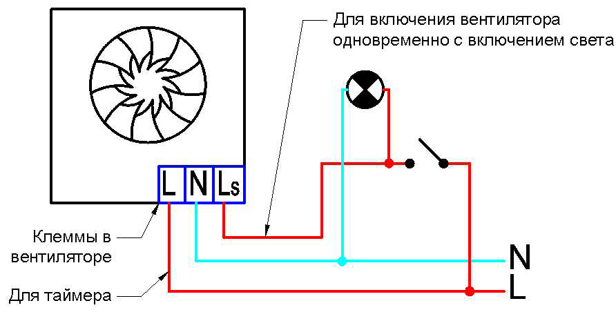
The figure clearly shows the connection diagram of the exhaust fan to the power supply using an timer, which allows you to turn off the fan some time after the visitor leaves the bathroom
It is somewhat more difficult to solve the problem of ventilating a bathroom when the ventilation duct borders on another room. In this case, you will have to create duct ventilation.
First you need to choose a place for the vent in the bathroom and toilet. Then it is necessary to draw up a plan for the placement of the ventilation duct, along which the air masses will move out.

When creating duct ventilation in the bathroom, a flexible corrugated box is used only in small areas where the installation of other structures is impossible or difficult
There are the following types of ventilation ducts:
- plastic round or rectangular section;
- hard or soft corrugated metal;
- metal, tin or galvanized, usually rectangular.
Plastic boxes are easier to install and lighter in weight than metal structures, while they are durable and easy to care for.
Therefore, plastic structures are confidently replacing metal from the construction market. Corrugated products are used extremely rarely, they are valid only for short distances and are used only in particularly difficult cases.
After the installation of the ventilation system is completed, it is necessary to check the operation of the equipment.

To create duct ventilation in the bathroom, metal or plastic boxes of rectangular or round cross section should be used.
Common mistakes when installing ventilation
It happens that the operation of a brand new ventilation system suddenly turns out to be unsatisfactory or is initially ineffective.
This may be due to one or more errors made during its installation. When figuring out how to properly ventilate the bathroom, you should immediately take into account these points.
Here are some of the most common mistakes:
- The ventilation duct is designed incorrectly, which makes it difficult for the movement of air masses.
- The tightness of the ventilation duct connections is broken.
- The fans are installed incorrectly and make too much noise.
- The channel passes through the living quarters in such a way that the ventilation noise interferes with the normal life of the family.
First you need to find out the cause of the problem, then fix it. A number of troubles can be avoided by paying attention to these points at the design stage of the ventilation system.
If this was not done, and problems appeared already during the operation of the structure, a serious alteration of the entire ventilation system may be required.
An alternative troubleshooting option is to use different types of noise absorbers to reduce unpleasant sound effects.
To improve the process of moving air masses, you may have to install a more powerful fan.
Sometimes excessive noise during fan operation indicates its incorrect installation, in which the so-called “alignment” was violated. In this case, it is enough to remove the device and install it again with strict adherence to the installation technology.
Usually, after this, the amount of noise from the operation of the fan is significantly reduced.
The supply type of ventilation in bathrooms is extremely rarely used, but if such a decision is nevertheless made, you should think about the temperature of the air entering from the outside.
In winter, the cold air flow can be extremely uncomfortable for bathroom visitors.
To solve this type of problem, the air entering the room is heated using special electrical appliances.

To ensure enough fresh air enters the bathroom, a beautiful grille is installed at the bottom of the door, which makes the room less airtight.
There are several common misconceptions that can negatively affect ventilation work. When designing and installing the system, remember that:
- an exhaust fan is not enough if a normal supply of fresh air is not provided to the room;
- a large and bulky duct ventilation system is not always more efficient than low-budget ventilation methods, if they are chosen correctly;
- the presence of an air conditioner in the house, as well as a purifier, ionizer, humidifier and other similar devices does not provide normal ventilation of the premises, since with their help fresh air does not enter the rooms.
Usually the design of the ventilation system for the bathroom is very simple, you can do it yourself.
But if some calculations or the implementation of a ventilation duct of a complex shape are required, and the novice master does not have experience in such work, it is better to consult professionals or completely entrust them with all the work.
The quality of ventilation cannot be neglected, since the health of the residents of the house depends on its condition.
CADvent program - new opportunities for designing ventilation systems
Elena Berdinsky (CAD Specialist, Lindab LLC)
The CADvent program is a development of the Swedish concern Lindab and has been one of the leading programs for the design of HVAC systems in Scandinavia, Western and Eastern Europe for more than 15 years.
Since 1965, Lindab's Ventilation business has been based on the development of system solutions for ventilation and air conditioning. Having vast experience in working with ventilation systems and working closely with engineers and installers, the company's specialists realized the need to create a program that would help to quickly and efficiently design ventilation systems, would include aerodynamic and acoustic calculations, would allow the creation of specifications for equipment and materials, and would have communication with a cost estimate program.
In 1992, the first release of the CADvent program was released, which quickly won the trust of consumers. CADvent combines powerful calculation functions with handy tools for drafting and designing ventilation systems. The program is constantly being improved in accordance with the requirements of the time and taking into account the needs of designers.
On the Russian market, Lindab presents a set of programs for calculating and designing ventilation, heating, plumbing and drainage systems, a program for simulating indoor climate. These are CADvent, DIMcomfort, DIMsilencer and TEKNOsim programs.
CADvent modules
The CADvent software is the basic HVAC design tool and comes in three main packages:
- CADvent Secure - design of ventilation systems. Closed databases of Lindab products;
- CADvent Link - design of ventilation systems. Open databases - in addition to the full list of Lindab products, which is in the program, you can upload databases from other manufacturers;
- CADvent Plus - design and calculation of ventilation and heating systems, drawing of water supply, sewerage, drainage and deluge systems. Open databases.
Depending on the design tasks, the designer can choose one or another package, and later, if necessary, upgrade to a version with more functionality.

Design and Calculation Functions
The CADvent program is an object-oriented application for AutoCAD and allows you to quickly and efficiently solve the whole range of tasks that arise in the implementation of projects for ventilation systems - this is the selection of equipment, the implementation of working drawings, all necessary system calculations, the creation of equipment and materials specifications.

The main functions of the CADvent program are:
- work on the AutoCAD 2004-2011 platform;
- 2D/3D design;
- automatic selection of sections of air ducts and pipelines;
- aerodynamic calculation / calculation of pressure losses in the system;
- automatic balancing of systems with the arrangement of throttle valves;
- noise calculation (acoustic calculation);
- associative labeling of system elements;
- quick changes to the system;
- automatic creation of plans/sections;
- automatic compilation of specifications of materials and equipment;
- the possibility of quick and easy replenishment of equipment bases;
- converting AutoCAD blocks into smart CADvent objects (data on dimensions, flow, dP, etc. are added);
- intelligent movement of elements with the function of maintaining system integrity using standard AutoCAD movement handles or a special CADvent function;
- automatic layer management;
- collision control;
- the ability to create non-standard elements;
- links to costing programs.
Working with equipment
The design of a ventilation system in CADvent is object-oriented, that is, the designer initially works with the equipment and system elements that he has. Each element included in the catalog is an intelligent object - a copy of a real-life equipment - and contains not only geometry data, but also the relationship between flow, pressure and speed, noise characteristics.
Databases of equipment and materials include thousands of items. In addition to the catalogs available in the program, the designer can independently create bases of air distributors and elements of ventilation systems or connect catalogs of air distributors from third-party manufacturers.
Intersection control
The collision control function helps the designer avoid costly design errors at all stages of the project and when coordinating the project with subcontractors.
Collision control allows you to control intersections between elements of a 3D model - elements of ventilation systems, intersections of air ducts and building envelopes created in AutoCAD Architecture (walls, windows, doors, floors, roofs, etc.), intersections with existing drawing with solids, intersections between all engineering systems of the building (ventilation, heating, plumbing, sewage and fire pipelines), as well as with AutoCAD MEP objects.
Interaction with AutoCAD
The program runs on AutoCAD 2004-2011, AutoCAD MEP (Autodesk Building Systems) 2007-2011, AutoCAD Architecture (Autodesk Architectural Desktop) specified versions, and AutoCAD Mechanical. The system requirements for installing CADvent are necessary and sufficient to install basic AutoCAD.
Standard AutoCAD editing functions - move, copy - are available for CADvent objects and do not affect their intelligence.
Interaction with the AutoCAD MEP program is implemented in a special program module available for all available configurations and allows you to import / export air ducts from the AutoCAD MEP program to CADvent for finalization, subsequent calculation and balancing of the system, drawing up specifications. When imported, AutoCAD MEP objects are automatically converted to CADvent objects, the objects have "handles" for moving, stretching, shrinking, etc.
Duct systems made in CADvent can be transferred to AutoCAD MEP in the same way, if necessary, modify, create cuts, specifications, etc.
Creation of working drawings
With the CADvent program you can create:
- plans on the mark;
- arbitrary sections;
- incisions.
A tinted isometric image of ventilation systems obtained using standard AutoCAD can be an excellent addition to working drawings and sometimes completely satisfies the customer.
An isometric view designer can easily build axonometry, create the necessary fragments and views.
The labeling of elements in the CADvent program is performed using labeling templates or text labels, which borrow the necessary data from the calculated model. Information is added to the drawing either at once for all objects of the same type with one click in accordance with the labeling settings, or in stages - element by element, at the request of the designer. The labeling is associative - when the characteristics of an element change (such as dimensions, cross section, air flow, pressure loss), the text label in the drawing is updated automatically, so there is no need to relabel the elements. The associativity of text labels not only saves the designer time, but also prevents incorrect information from appearing on the drawing.
Creation of working documentation
The CADvent program allows you to automatically create bills of materials and equipment, system calculation sheets almost with the click of a single button. The principle of drawing up a specification based on an existing 3D model is simple - everything that is on the drawing is automatically entered into the specification. At the same time, the possibility of data loss is minimized, the possibility of forgetting any element or miscalculating when determining the length of an air duct or pipeline is eliminated.
At the same time, the designer always has the opportunity to create a specification for a part of the ventilation system - for example, for a floor plan or a specific system, a specification for selected elements. All spreadsheet documents can be transferred to MS Excel or saved as PDF.
Visualization
If you need to create presentation views of systems at any stage of design for a visual presentation of the project to the customer or potential customers, you can use the visualization function built into the program.
The program makes it possible to create a perspective view of systems with the task of elevation, point and direction of view. The perspective view can also be supplemented with the necessary inscription and clarifying notes.
Additional utility programs
In addition to the CADvent functionality, the designer can use special programs that allow simulating the indoor climate (TEKNOsim), selecting diffusers taking into account the requirements for air velocity in the working area and noise (DIMcomfort), selecting and arranging silencers (DIMsilencer).


DIMsilencer program
DIMsilencer allows you to match round, rectangular and corner silencers. There are several silencer options available:
- according to the required sound power Lwa dB(A) after the silencer;
- according to the required noise level by frequency (Hz) after the silencer;
- for noise reduction;
- by its own noise generation.
As a result of the calculation, the user sees all the parameters: noise before the silencer, noise generation by the silencer itself, noise reduction, noise after the silencer, noise by octaves, as well as the technical characteristics of the selected silencer.
DIMcomfort program
DIMcomfort allows you to select air-distributing devices - diffusers, grilles, taking into account the air speed in the working area and noise. After specifying the type and geometry of the room, the amount of air (or the frequency of air exchange) and the temperature of the supplied air, the program automatically generates a three-dimensional model of the room. Selected air distributors are placed in the room. The designer can see how the required noise level in the room is maintained, the air speed in the working area, how the air flow from the air diffusers is distributed, and how the position of the air diffuser affects all these parameters.
The selected air terminals can be exported to the CADvent software with data on flow, pressure loss and noise saved.
The DIMcomfort and DIMsilencer programs are shareware and can be used independently of the CADvent program, in a separate installation, or in conjunction with CADvent. The programs are integrated into the CADvent interface, which allows you to instantly and losslessly carry out the necessary data exchange.
Detailed information on the CADvent program can be obtained on the website of the Russian representative office of the Lindab concern www.lindab.ru or by contacting the CADvent technical support service.