Repair of LED lamps using examples. How to make a huge LED DIY LED boards
So, after disassembling and removing a fully functional converter from the burnt energy saver, the details of which will still serve us for further designs, we have a good plastic case with an E28 threaded base, which just begs to be used for a homemade LED light bulb. And the bulbs (light diffusers) were lying around from early weak LED lamps, which work without them at full brightness - they won’t go to waste. I still had a piece of RGB tape made from six LEDs, so I decided to use these things to make a night light for the aquarium. I found a suitable circuit, a lamp power supply circuit from the site Electronic Circuits, followed it with a signet, and this is what happened:
Lamp circuit board

You can change the design of the printed circuit board to suit your LED elements - here is the Lay file. But on this RGB lamp board the polarity of the LEDs was set incorrectly; there is a corrected version on the forum. The brightness turned out to be maximum, since the LEDs receive about 20 mA with a capacitor of 0.33x400V.

The capacity of this capacitor is selected based on the operating current of the LEDs. So, at 0.5 µF, such a circuit will provide approximately 30 mA. The voltage will be limited by the zener diodes.


About the power of LED lamps
For good, or rather the minimum acceptable lighting of a room, you need a 10-watt LED lamp with a luminous flux of 1000 lumens and above. You can also collect these, but you need very bright LEDs, and they are only made to order. And homemade lamps with powers of up to about 3 W are more suitable for illuminating small rooms, corridors, bathrooms, etc.
In our previous articles, we have described many times the process of making a board for installing various LED modules in a car. Using the LUT method provides very wide opportunities for realizing the most daring ideas. However, lately, more and more often, our clients have been asking the question of how to make a board using this technology that would be larger than a standard A4 sheet. The fact is that the vast majority have a printer that is capable of printing only in A4 format and, therefore, it is not possible to produce larger boards using the LUT method. In this article we will try to describe in detail how to use. The LUT method of making composite boards using the example of “LED cilia”.
The LED module that needs to be created has a length of 43 cm. And since there is an A4 format printer and scanner available (A4 length is 29.7 cm, if anything), the board must be made as a composite board.
First, let's draw a board and print it on 2 different A4 sheets. It is important to make the board a little oversized so that you can remove the excess later. Using the LUT method we transfer the image to tectolite.
We put connection marks on the boards to make it easier to mount a solid board. Now the boards are ready for etching.
We cut out the excess textolite and move on to etching.
.jpg)
Carefully cut off the excess along the cut line. The edges should be as flat as possible so that both boards fit together and look like one piece.
.jpg)
We remove everything unnecessary and start soldering the LEDs and resistors.
.jpg)
On the back side of the board we solder the boards themselves together.

The board is ready.

Now it can easily be used as LED eyelashes. All you need to do is select the diffuser and you can install the module in the car.
Due to low energy consumption, theoretical durability and lower prices, incandescent and energy-saving lamps are rapidly replacing them. But, despite the declared service life of up to 25 years, they often burn out without even serving the warranty period.
Unlike incandescent lamps, 90% of burnt-out LED lamps can be successfully repaired with your own hands, even without special training. The examples presented will help you repair failed LED lamps.
Before you start repairing an LED lamp, you need to understand its structure. Regardless of the appearance and type of LEDs used, all LED lamps, including filament bulbs, are designed the same. If you remove the walls of the lamp body, you can see the driver inside, which is a printed circuit board with radio elements installed on it.

Any LED lamp is designed and works as follows. The supply voltage from the contacts of the electric cartridge is supplied to the terminals of the base. Two wires are soldered to it, through which voltage is supplied to the driver input. From the driver, the DC supply voltage is supplied to the board on which the LEDs are soldered.
The driver is an electronic unit - a current generator that converts the supply voltage into the current required to light the LEDs.
Sometimes, to diffuse light or protect against human contact with unprotected conductors of a board with LEDs, it is covered with diffusing protective glass.
About filament lamps
In appearance, a filament lamp is similar to an incandescent lamp. The design of filament lamps differs from LED lamps in that they do not use a board with LEDs as light emitters, but a sealed glass flask filled with gas, in which one or more filament rods are placed. The driver is located in the base.

The filament rod is a glass or sapphire tube with a diameter of about 2 mm and a length of about 30 mm, on which 28 miniature LEDs coated in series with a phosphor are attached and connected. One filament consumes about 1 W of power. My operating experience shows that filament lamps are much more reliable than those made on the basis of SMD LEDs. I believe that over time they will replace all other artificial light sources.
Examples of LED lamp repairs
Attention, the electrical circuits of the LED lamp drivers are galvanically connected to the phase of the electrical network and therefore extreme care should be taken. Touching an unprotected part of a person’s body to exposed parts of a circuit connected to an electrical network can cause serious damage to health, including cardiac arrest.
LED lamp repair
ASD LED-A60, 11 W on SM2082 chip
Currently, powerful LED light bulbs have appeared, the drivers of which are assembled on SM2082 type chips. One of them worked for less than a year and ended up being repaired. The light went out randomly and came on again. When you tapped it, it responded with light or extinguishing. It became obvious that the problem was poor contact.

To get to the electronic part of the lamp, you need to use a knife to pick up the diffuser glass at the point of contact with the body. Sometimes it is difficult to separate the glass, since when it is seated, silicone is applied to the fixing ring.

After removing the light-scattering glass, access to the LEDs and the SM2082 current generator microcircuit became available. In this lamp, one part of the driver was mounted on an aluminum LED printed circuit board, and the second on a separate one.

An external inspection did not reveal any defective soldering or broken tracks. I had to remove the board with LEDs. To do this, the silicone was first cut off and the board was pryed off by the edge with a screwdriver blade.
To get to the driver located in the lamp body, I had to unsolder it by heating two contacts with a soldering iron at the same time and moving it to the right.

On one side of the driver circuit board, only an electrolytic capacitor with a capacity of 6.8 μF for a voltage of 400 V was installed.

A diode bridge and two series-connected resistors with a nominal value of 510 kOhm were installed on the reverse side of the driver board.

In order to figure out which of the boards the contact was missing, we had to connect them, observing the polarity, using two wires. After tapping the boards with the handle of a screwdriver, it became obvious that the fault lies in the board with the capacitor or in the contacts of the wires coming from the base of the LED lamp.

Since the soldering did not raise any suspicions, I first checked the reliability of the contact in the central terminal of the base. It can be easily removed if you pry it over the edge with a knife blade. But the contact was reliable. Just in case, I tinned the wire with solder.
It is difficult to remove the screw part of the base, so I decided to use a soldering iron to solder the soldering wires coming from the base. When I touched one of the soldering joints, the wire became exposed. A “cold” solder was detected. Since there was no way to get to the wire to strip it, I had to lubricate it with FIM active flux and then solder it again.

After assembly, the LED lamp consistently emitted light, despite hitting it with the handle of a screwdriver. Checking the light flux for pulsations showed that they are significant with a frequency of 100 Hz. Such an LED lamp can only be installed in luminaires for general lighting.
Driver circuit diagram
LED lamp ASD LED-A60 on SM2082 chip
The electrical circuit of the ASD LED-A60 lamp, thanks to the use of a specialized SM2082 microcircuit in the driver to stabilize the current, turned out to be quite simple.

The driver circuit works as follows. The AC supply voltage is supplied through fuse F to the rectifier diode bridge assembled on the MB6S microassembly. Electrolytic capacitor C1 smoothes out ripples, and R1 serves to discharge it when the power is turned off.
From the positive terminal of the capacitor, the supply voltage is supplied directly to the LEDs connected in series. From the output of the last LED, the voltage is supplied to the input (pin 1) of the SM2082 microcircuit, the current in the microcircuit is stabilized and then from its output (pin 2) it goes to the negative terminal of capacitor C1.
Resistor R2 sets the amount of current flowing through the HL LEDs. The amount of current is inversely proportional to its rating. If the value of the resistor is decreased, the current will increase; if the value is increased, the current will decrease. The SM2082 microcircuit allows you to adjust the current value with a resistor from 5 to 60 mA.
LED lamp repair
ASD LED-A60, 11 W, 220 V, E27
The repair included another ASD LED-A60 LED lamp, similar in appearance and with the same technical characteristics as the one repaired above.

When turned on, the lamp came on for a moment and then did not shine. This behavior of LED lamps is usually associated with a driver failure. So I immediately started disassembling the lamp.
The light-diffusing glass was removed with great difficulty, since along the entire line of contact with the body it was, despite the presence of a retainer, generously lubricated with silicone. To separate the glass, I had to look for a pliable place along the entire line of contact with the body using a knife, but still there was a crack in the body.

To gain access to the lamp driver, the next step was to remove the LED printed circuit board, which was pressed along the contour into the aluminum insert. Despite the fact that the board was aluminum and could be removed without fear of cracks, all attempts were unsuccessful. The board held tight.
It was also not possible to remove the board together with the aluminum insert, since it fit tightly to the case and was seated with the outer surface on silicone.

I decided to try removing the driver board from the base side. To do this, first, a knife was pryed out of the base and the central contact was removed. To remove the threaded part of the base, we had to slightly bend its upper flange so that the core points would disengage from the base.
The driver became accessible and was freely extended to a certain position, but it was not possible to remove it completely, although the conductors from the LED board were sealed off.

The LED board had a hole in the center. I decided to try to remove the driver board by hitting its end through a metal rod threaded through this hole. The board moved a few centimeters and hit something. After further blows, the lamp body cracked along the ring and the board with the base of the base separated.
As it turned out, the board had an extension whose shoulders rested against the lamp body. It looks like the board was shaped this way to limit movement, although it would have been enough to fix it with a drop of silicone. Then the driver would be removed from either side of the lamp.

The 220 V voltage from the lamp base is supplied through a resistor - fuse FU to the MB6F rectifier bridge and is then smoothed out by an electrolytic capacitor. Next, the voltage is supplied to the SIC9553 chip, which stabilizes the current. Parallel connected resistors R20 and R80 between pins 1 and 8 MS set the amount of LED supply current.

The photo shows a typical electrical circuit diagram given by the manufacturer of the SIC9553 chip in the Chinese datasheet.

This photo shows the appearance of the LED lamp driver from the installation side of the output elements. Since space allowed, to reduce the pulsation coefficient of the light flux, the capacitor at the driver output was soldered to 6.8 μF instead of 4.7 μF.

If you have to remove the drivers from the body of this lamp model and cannot remove the LED board, you can use a jigsaw to cut the lamp body around the circumference just above the screw part of the base.

In the end, all my efforts to extract the driver turned out to be useful only in understanding the structure of the LED lamp. The driver turned out to be OK.
The flash of the LEDs at the moment of switching on was caused by a breakdown in the crystal of one of them as a result of a voltage surge when the driver was started, which misled me. It was necessary to ring the LEDs first.
An attempt to test the LEDs with a multimeter was unsuccessful. The LEDs did not light up. It turned out that two light-emitting crystals connected in series are installed in one case, and in order for the LED to start flowing current, it is necessary to apply a voltage of 8 V to it.
A multimeter or tester turned on in resistance measurement mode produces a voltage within 3-4 V. I had to check the LEDs using a power supply, supplying 12 V to each LED through a 1 kOhm current-limiting resistor.
There was no replacement LED available, so the pads were shorted with a drop of solder instead. This is safe for driver operation, and the power of the LED lamp will decrease by only 0.7 W, which is almost imperceptible.

After repairing the electrical part of the LED lamp, the cracked body was glued with quick-drying Moment super glue, the seams were smoothed by melting the plastic with a soldering iron and leveled with sandpaper.

Just for fun, I did some measurements and calculations. The current flowing through the LEDs was 58 mA, the voltage was 8 V. Therefore, the power supplied to one LED was 0.46 W. With 16 LEDs, the result is 7.36 W, instead of the declared 11 W. Perhaps the manufacturer has indicated the total power consumption of the lamp, taking into account losses in the driver.
The service life of the ASD LED-A60, 11 W, 220 V, E27 LED lamp declared by the manufacturer raises serious doubts in my mind. In the small volume of the plastic lamp body, with low thermal conductivity, significant power is released - 11 W. As a result, the LEDs and the driver operate at the maximum permissible temperature, which leads to accelerated degradation of their crystals and, as a consequence, to a sharp reduction in their time between failures.
LED lamp repair
LED smd B35 827 ERA, 7 W on BP2831A chip
An acquaintance shared with me that he bought five light bulbs like in the photo below, and after a month they all stopped working. He managed to throw away three of them, and, at my request, brought two for repairs.

The light bulb worked, but instead of bright light it emitted a flickering weak light with a frequency of several times per second. I immediately assumed that the electrolytic capacitor had swollen; usually, if it fails, the lamp begins to emit light like a strobe.

The light-scattering glass came off easily, it was not glued. It was fixed by a slot on its rim and a protrusion in the lamp body.

The driver was secured using two solders to a printed circuit board with LEDs, as in one of the lamps described above.

A typical driver circuit on the BP2831A chip taken from the datasheet is shown in the photograph. The driver board was removed and all simple radio elements were checked, they all turned out to be in good order. I had to start checking the LEDs.

The LEDs in the lamp were installed of an unknown type with two crystals in the housing and inspection did not reveal any defects. By connecting the leads of each LED in series, I quickly identified the faulty one and replaced it with a drop of solder, as in the photo.
The light bulb worked for a week and was repaired again. Shorted the next LED. A week later I had to short-circuit another LED, and after the fourth I threw out the light bulb because I was tired of repairing it.
The reason for the failure of light bulbs of this design is obvious. LEDs overheat due to insufficient heat sink surface, and their service life is reduced to hundreds of hours.
Why is it permissible to short-circuit the terminals of burnt-out LEDs in LED lamps?
The LED lamp driver, unlike a constant voltage power supply, produces a stabilized current value at the output, not a voltage. Therefore, regardless of the load resistance within the specified limits, the current will always be constant and, therefore, the voltage drop across each of the LEDs will remain the same.
Therefore, as the number of series-connected LEDs in the circuit decreases, the voltage at the driver output will also decrease proportionally.
For example, if 50 LEDs are connected in series to the driver, and each of them drops a voltage of 3 V, then the voltage at the driver output is 150 V, and if you short-circuit 5 of them, the voltage will drop to 135 V, and the current will not change.

But the efficiency of the driver assembled according to this scheme will be low and the power loss will be more than 50%. For example, for an LED light bulb MR-16-2835-F27 you will need a 6.1 kOhm resistor with a power of 4 watts. It turns out that the resistor driver will consume power that exceeds the power consumption of LEDs and placing it in a small LED lamp housing will be unacceptable due to the release of more heat.
But if there is no other way to repair an LED lamp and it is very necessary, then the resistor driver can be placed in a separate housing; anyway, the power consumption of such an LED lamp will be four times less than incandescent lamps. It should be noted that the more LEDs connected in series in a light bulb, the higher the efficiency will be. With 80 series-connected SMD3528 LEDs, you will need an 800 Ohm resistor with a power of only 0.5 W. The capacitance of capacitor C1 will need to be increased to 4.7 µF.
Finding faulty LEDs
After removing the protective glass, it becomes possible to check the LEDs without peeling off the printed circuit board. First of all, a careful inspection of each LED is carried out. If even the smallest black dot is detected, not to mention blackening of the entire surface of the LED, then it is definitely faulty.
When inspecting the appearance of the LEDs, you need to carefully examine the quality of the soldering of their terminals. One of the light bulbs being repaired turned out to have four LEDs that were poorly soldered.

The photo shows a light bulb that had very small black dots on its four LEDs. I immediately marked the faulty LEDs with crosses so that they were clearly visible.
Faulty LEDs may not have any changes in appearance. Therefore, it is necessary to check each LED with a multimeter or pointer tester turned on in resistance measurement mode.
There are LED lamps in which standard LEDs are installed in appearance, in the housing of which two crystals connected in series are mounted at once. For example, lamps of the ASD LED-A60 series. To test such LEDs, it is necessary to apply a voltage of more than 6 V to its terminals, and any multimeter produces no more than 4 V. Therefore, checking such LEDs can only be done by applying a voltage of more than 6 (recommended 9-12) V to them from the power source through a 1 kOhm resistor .

The LED is checked like a regular diode; in one direction the resistance should be equal to tens of megaohms, and if you swap the probes (this changes the polarity of the voltage supply to the LED), then it should be small, and the LED may glow dimly.

When checking and replacing LEDs, the lamp must be fixed. To do this, you can use a suitable sized round jar.
You can check the serviceability of the LED without an additional DC source. But this verification method is possible if the light bulb driver is working properly. To do this, it is necessary to apply supply voltage to the base of the LED light bulb and short-circuit the terminals of each LED in series with each other using a wire jumper or, for example, the jaws of metal tweezers.

If suddenly all the LEDs light up, it means that the shorted one is definitely faulty. This method is suitable if only one LED in the circuit is faulty. With this method of checking, it is necessary to take into account that if the driver does not provide galvanic isolation from the electrical network, as for example in the diagrams above, then touching the LED solders with your hand is unsafe.
If one or even several LEDs turn out to be faulty and there is nothing to replace them with, then you can simply short-circuit the contact pads to which the LEDs were soldered. The light bulb will work with the same success, only the luminous flux will decrease slightly.
Other LED lamp faults
If checking the LEDs showed their serviceability, then the reason for the light bulb’s inoperability lies in the driver or in the soldering areas of the current-carrying conductors.

For example, in this light bulb a cold solder connection was found on the conductor supplying power to the printed circuit board. The soot released due to poor soldering even settled on the conductive paths of the printed circuit board. The soot was easily removed by wiping with a rag soaked in alcohol. The wire was soldered, stripped, tinned and re-soldered into the board. I was lucky with the repair of this light bulb.
Of the ten failed bulbs, only one had a faulty driver and a broken diode bridge. The driver repair consisted of replacing the diode bridge with four IN4007 diodes, designed for a reverse voltage of 1000 V and a current of 1 A.
Soldering SMD LEDs
To replace a faulty LED, it must be desoldered without damaging the printed conductors. You also need to remove the replacement LED from the donor board without damaging it.
It is almost impossible to desolder SMD LEDs with a simple soldering iron without damaging their housing. But if you use a special tip for a soldering iron or put an attachment made of copper wire on a standard tip, then the problem can be easily solved.

LEDs have polarity and when replacing, you need to install it correctly on the printed circuit board. Typically, printed conductors follow the shape of the leads on the LED. Therefore, a mistake can only be made if you are inattentive. To seal an LED, just install it on a printed circuit board and heat its ends with the contact pads with a 10-15 W soldering iron.
If the LED burns out like carbon, and the printed circuit board underneath is charred, then before installing a new LED, you must clean this area of the printed circuit board from burning, since it is a current conductor. When cleaning, you may find that the LED solder pads are burnt or peeled off.

In this case, the LED can be installed by soldering it to adjacent LEDs if the printed traces lead to them. To do this, you can take a piece of thin wire, bend it in half or three times, depending on the distance between the LEDs, tin it and solder it to them.
Repair of LED lamp series "LL-CORN" (corn lamp)
E27 4.6W 36x5050SMD
The design of the lamp, which is popularly called a corn lamp, shown in the photo below differs from the lamp described above, therefore the repair technology is different.

The design of LED SMD lamps of this type is very convenient for repair, since there is access to test the LEDs and replace them without disassembling the lamp body. True, I still disassembled the light bulb for fun in order to study its structure.

Checking the LEDs of an LED corn lamp is no different from the technology described above, but we must take into account that the SMD5050 LED housing contains three LEDs at once, usually connected in parallel (three dark points of the crystals are visible on the yellow circle), and during testing all three should glow.

A faulty LED can be replaced with a new one or short-circuited with a jumper. This will not affect the reliability of the lamp, only the luminous flux will decrease slightly, imperceptibly to the eye.
The driver of this lamp is assembled according to the simplest circuit, without an isolating transformer, so touching the LED terminals when the lamp is on is unacceptable. Lamps of this design must not be installed in lamps that can be reached by children.
If all the LEDs are working, it means the driver is faulty, and the lamp will have to be disassembled to get to it.

To do this, you need to remove the rim from the side opposite the base. Using a small screwdriver or a knife blade, try in a circle to find the weak spot where the rim is glued the worst. If the rim gives way, then using the tool as a lever, the rim will easily come off around the entire perimeter.

The driver was assembled according to the electrical circuit, like the MR-16 lamp, only C1 had a capacity of 1 µF, and C2 - 4.7 µF. Due to the fact that the wires going from the driver to the lamp base were long, the driver was easily removed from the lamp body. After studying its circuit diagram, the driver was inserted back into the housing, and the bezel was glued into place with transparent Moment glue. The failed LED was replaced with a working one.
Repair of LED lamp "LL-CORN" (corn lamp)
E27 12W 80x5050SMD
When repairing a more powerful lamp, 12 W, there were no failed LEDs of the same design and in order to get to the drivers, we had to open the lamp using the technology described above.

This lamp gave me a surprise. The wires leading from the driver to the socket were short, and it was impossible to remove the driver from the lamp body for repair. I had to remove the base.

The lamp base was made of aluminum, cored around the circumference and held tightly. I had to drill out the mounting points with a 1.5 mm drill. After this, the base, pryed off with a knife, was easily removed.
But you can do without drilling the base if you use the edge of a knife to pry it around the circumference and slightly bend its upper edge. You should first put a mark on the base and body so that the base can be conveniently installed in place. To securely fasten the base after repairing the lamp, it will be enough to put it on the lamp body in such a way that the punched points on the base fall into the old places. Next, press these points with a sharp object.
Two wires were connected to the thread with a clamp, and the other two were pressed into the central contact of the base. I had to cut these wires.

As expected, there were two identical drivers, feeding 43 diodes each. They were covered with heat shrink tubing and taped together. In order for the driver to be placed back into the tube, I usually carefully cut it along the printed circuit board from the side where the parts are installed.

After repair, the driver is wrapped in a tube, which is fixed with a plastic tie or wrapped with several turns of thread.

In the electrical circuit of the driver of this lamp, protection elements are already installed, C1 for protection against pulse surges and R2, R3 for protection against current surges. When checking the elements, resistors R2 were immediately found to be open on both drivers. It appears that the LED lamp was supplied with a voltage that exceeded the permissible voltage. After replacing the resistors, I didn’t have a 10 ohm one at hand, so I set it to 5.1 ohms, and the lamp started working.
Repair of LED lamp series "LLB" LR-EW5N-5
The appearance of this type of light bulb inspires confidence. Aluminum body, high quality workmanship, beautiful design.

The design of the light bulb is such that disassembling it without the use of significant physical effort is impossible. Since the repair of any LED lamp begins with checking the serviceability of the LEDs, the first thing we had to do was remove the plastic protective glass.

The glass was fixed without glue on a groove made in the radiator with a collar inside it. To remove the glass, you need to use the end of a screwdriver, which will go between the fins of the radiator, to lean on the end of the radiator and, like a lever, lift the glass up.

Checking the LEDs with a tester showed that they are working properly, therefore, the driver is faulty and we need to get to it. The aluminum board was secured with four screws, which I unscrewed.

But contrary to expectations, behind the board there was a radiator plane, lubricated with heat-conducting paste. The board had to be returned to its place and the lamp continued to be disassembled from the base side.

Due to the fact that the plastic part to which the radiator was attached was held very tightly, I decided to go the proven route, remove the base and remove the driver through the opened hole for repair. I drilled out the core points, but the base was not removed. It turned out that it was still attached to the plastic due to the threaded connection.

I had to separate the plastic adapter from the radiator. It held up just like the protective glass. To do this, a cut was made with a hacksaw for metal at the junction of the plastic with the radiator and by turning a screwdriver with a wide blade, the parts were separated from each other.

After unsoldering the leads from the LED printed circuit board, the driver became available for repair. The driver circuit turned out to be more complex than previous light bulbs, with an isolation transformer and a microcircuit. One of the 400 V 4.7 µF electrolytic capacitors was swollen. I had to replace it.

A check of all semiconductor elements revealed a faulty Schottky diode D4 (pictured below on the left). There was an SS110 Schottky diode on the board, which was replaced with an existing analog 10 BQ100 (100 V, 1 A). The forward resistance of Schottky diodes is two times less than that of ordinary diodes. The LED light came on. The second light bulb had the same problem.
Repair of LED lamp series "LLB" LR-EW5N-3
This LED lamp is very similar in appearance to the "LLB" LR-EW5N-5, but its design is slightly different.

If you look closely, you can see that at the junction between the aluminum radiator and the spherical glass, unlike the LR-EW5N-5, there is a ring in which the glass is secured. To remove the protective glass, use a small screwdriver to pry it at the junction with the ring.

Three nine super-bright crystal LEDs are installed on an aluminum printed circuit board. The board is screwed to the heatsink with three screws. Checking the LEDs showed their serviceability. Therefore, the driver needs to be repaired. Having experience in repairing a similar LED lamp "LLB" LR-EW5N-5, I did not unscrew the screws, but unsoldered the current-carrying wires coming from the driver and continued disassembling the lamp from the base side.

The plastic connecting ring between the base and the radiator was removed with great difficulty. At the same time, part of it broke off. As it turned out, it was screwed to the radiator with three self-tapping screws. The driver was easily removed from the lamp body.

The screws that fasten the plastic ring of the base are covered by the driver and are difficult to see, but they are on the same axis with the thread to which the adapter part of the radiator is screwed. Therefore, you can reach them with a thin Phillips screwdriver.

The driver turned out to be assembled according to a transformer circuit. Checking all elements except the microcircuit did not reveal any failures. Consequently, the microcircuit is faulty; I couldn’t even find a mention of its type on the Internet. The LED light bulb could not be repaired; it will be useful for spare parts. But I studied its structure.
Repair of LED lamp series "LL" GU10-3W
At first glance, it turned out to be impossible to disassemble a burnt-out GU10-3W LED light bulb with protective glass. An attempt to remove the glass resulted in its chipping. When great force was applied, the glass cracked.

By the way, in the lamp marking, the letter G means that the lamp has a pin base, the letter U means that the lamp belongs to the class of energy-saving light bulbs, and the number 10 means the distance between the pins in millimeters.

LED light bulbs with a GU10 base have special pins and are installed in a socket with a rotation. Thanks to the expanding pins, the LED lamp is pinched in the socket and held securely even when shaking.

In order to disassemble this LED light bulb, I had to drill a hole with a diameter of 2.5 mm in its aluminum case at the level of the surface of the printed circuit board. The drilling location must be chosen in such a way that the drill does not damage the LED when exiting. If you don’t have a drill at hand, you can make a hole with a thick awl.

Next, a small screwdriver is inserted into the hole and, acting like a lever, the glass is lifted. I removed the glass from two light bulbs without any problems. If checking the LEDs with a tester shows their serviceability, then the printed circuit board is removed.

After separating the board from the lamp body, it immediately became obvious that the current-limiting resistors had burned out in both one and the other lamp. The calculator determined their nominal value from the stripes, 160 Ohms. Since the resistors burned out in LED bulbs of different batches, it is obvious that their power, judging by the size of 0.25 W, does not correspond to the power released when the driver operates at the maximum ambient temperature.

The driver circuit board was well filled with silicone, and I did not disconnect it from the board with the LEDs. I cut off the leads of the burnt resistors at the base and soldered them to more powerful resistors that were on hand. In one lamp I soldered a 150 Ohm resistor with a power of 1 W, in the second two in parallel with 320 Ohms with a power of 0.5 W.

In order to prevent accidental contact of the resistor terminal, to which the mains voltage is connected, with the metal body of the lamp, it was insulated with a drop of hot-melt adhesive. It is waterproof and an excellent insulator. I often use it for sealing, insulating and securing electrical wires and other parts.

Hot-melt adhesive is available in sticks with diameters of 7, 12, 15 and 24 mm in different colors, from transparent to black. It melts, depending on the brand, at a temperature of 80-150°, which allows it to be melted using an electric soldering iron. It is enough to cut a piece of the rod, place it in the right place and heat it. Hot-melt glue will acquire the consistency of May honey. After cooling it becomes hard again. When reheated, it becomes liquid again.

After replacing the resistors, the functionality of both bulbs was restored. All that remains is to secure the printed circuit board and protective glass in the lamp body.

When repairing LED lamps, I used liquid nails “Mounting” to secure printed circuit boards and plastic parts. The glue is odorless, adheres well to the surfaces of any materials, remains plastic after drying, and has sufficient heat resistance.

It is enough to take a small amount of glue on the end of a screwdriver and apply it to the places where the parts come into contact. After 15 minutes the glue will already hold.

When gluing the printed circuit board, in order not to wait, holding the board in place, since the wires were pushing it out, I additionally fixed the board at several points using hot glue.
The LED lamp began to flash like a strobe light
I had to repair a couple of LED lamps with drivers assembled on a microcircuit, the malfunction of which was the light blinking at a frequency of about one hertz, like in a strobe light.
One instance of the LED lamp began to blink immediately after being turned on for the first few seconds and then the lamp began to shine normally. Over time, the duration of the lamp's blinking after switching on began to increase, and the lamp began to blink continuously. The second instance of the LED lamp suddenly began blinking continuously.

After disassembling the lamps, it turned out that the electrolytic capacitors installed immediately after the rectifier bridges in the drivers had failed. It was easy to determine the malfunction, since the capacitor housings were swollen. But even if the capacitor looks free of external defects in appearance, then the repair of an LED light bulb with a stroboscopic effect must still begin with its replacement.
After replacing the electrolytic capacitors with working ones, the stroboscopic effect disappeared and the lamps began to shine normally.
Online calculators for determining resistor values
by color marking
When repairing LED lamps, it becomes necessary to determine the resistor value. According to the standard, modern resistors are marked by applying colored rings to their bodies. 4 colored rings are applied to simple resistors, and 5 to high-precision resistors.
LEDs and products based on them are becoming increasingly popular. LED light bulbs and lamps are systematically displacing traditional light sources from store shelves. This semiconductor device also cannot leave radio amateurs indifferent, and the question increasingly arises: how to make an LED with your own hands?
The LED itself is quite complex to manufacture, and it is impossible to repeat the technological process outside of production conditions. Growing a crystal, packaging, applying phosphor - all this requires complex, expensive equipment. However, the further life path of an LED that has left production can be very diverse. LEDs are used in monitor backlighting, display, lighting and many other areas. They open up enormous opportunities for both professional developers and ordinary DIY enthusiasts.
In order for the LED to work, it needs to be soldered onto the board; such a unit will already be called an LED module. The module may include one or more light-emitting diodes.
Unlike indicator LEDs, which have long pins for soldering into holes, high-power lighting LEDs are primarily manufactured in surface-mount packages. Therefore, soldering them onto a board with your own hands is much more difficult, and the printed circuit boards themselves for such LEDs come in different types.
Fiberglass can be used only if the power is low, no more than a watt per LED, to avoid overheating. In this case, the space near the diode must be metalized, and sometimes “studded” with vias to quickly dissipate heat to the second side of the board. Although the heatsink from such a board turns out to be unimportant, it has a significant advantage - you can easily make it yourself using the good old “printer and iron” technology.
For optimal heat dissipation, a high-power LED is usually mounted on an MCPCB (Metal Core Printed Circuit Board) board.
It is an aluminum plate that has copper printed conductors on the surface, separated from the base by a thin dielectric oxide film. Such boards usually have a thickness of 1.5-2 mm, they are much more expensive than textolite ones and, as a rule, they can only be obtained in finished form, already wired for specific types of LEDs. You won’t be able to make such a board yourself - you need to have specialized production. However, recently, almost all domestic manufacturers of printed circuit boards have begun to provide services for the production of MCPCBs, and if there is a strong desire to produce your own unique LED module, then today you can realize it. It won't be cheap.
Soldering an LED onto an MCPCB board presents certain difficulties:
- when you try to solder a diode with a regular soldering iron or soldering station, the board becomes a significant hindrance - a radiator that removes heat from the contact pad, preventing it from heating up properly, so you have to use a powerful soldering iron;
- In addition to the cathode and anode, a powerful LED usually also has a terminal for heat removal, which is a flat platform located at the bottom of the LED housing, i.e. inaccessible to the soldering iron tip.
A typical board for such LEDs is shown in the figure below.

Because of its bizarre shape, this board is called a “star”. In the center is a LED seat, in this case XPE from CREE. The LED itself looks like this

Soldering the LED to the star can be done using a hot air gun, but this must be done with great care so as not to damage the lens. You should also make sure that the air flow does not dislodge the LED. You should not overuse solder paste; if you apply too much, the body may “float” and you will end up with a skew.
If you need to solder a large number of LEDs, for example, a module in the form of a long ruler, then a hair dryer is definitely not the best option.
There is a more efficient installation method. An old flat iron can be an ideal tool for “baking” LED modules. It is installed with the sole side up and heated to about 230 degrees. Then an aluminum board with pre-applied flux, solder paste and installed LEDs is carefully installed on it. You can visually see when the board heats up, the solder paste melts and clear solder joints form. The main thing is not to overexpose it - the LED can be exposed to such temperatures only for a few tens of seconds, otherwise it can be damaged or lose a significant share of the luminous flux. In this way, you can solder several dozen LEDs simultaneously.
8x8 LED Matrix Displays come in a variety of sizes and are fun to work with. Large industrial assemblies measure around 60 x 60 mm. However, if you are looking for much larger LED matrices, they are difficult to find.
In this project we will be building a really large LED matrix LED display that is made up of several large 8x8 LED modules connected in series with each other. Each of these modules measures approximately 144 x 144 mm.
The special thing about this display is that you can look at the background behind it if necessary. This gives you the freedom to use these displays creatively, such as placing them in front of glass panels so you can see what's happening behind the display.

For this project we will use 10mm. You can use other sizes. Commonly available sizes are 3mm, 5mm, 8mm, and 10mm.

Although the display is not designed to work with any microcontroller, we will use popular Arduino boards and connect it via SPI using only 3 signal wires.

To build this project, basic knowledge of electronics and component soldering is required, as well as some knowledge of using Arduino. Firmware .
Here you need to solder the LEDs together using the long LED legs. You can use any size and color of LED, but the leg length (more than 23mm) must be long enough to bend and solder them together. The LEDs are arranged in an 8x8 matrix, where the cathodes are soldered together for the rows, and the anodes are soldered together for the columns.

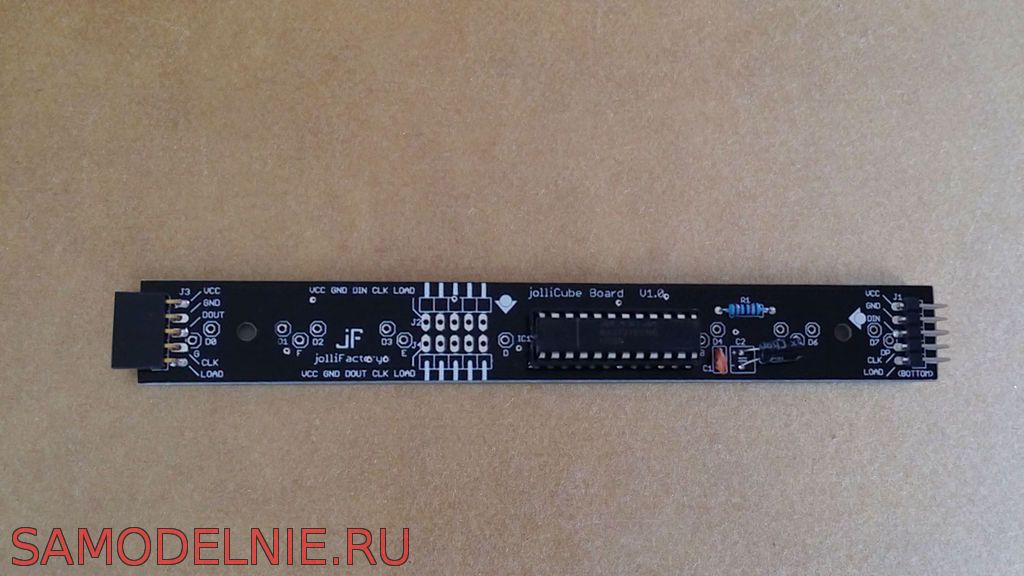
The MAX7219 driver controls the dynamic display of the LED matrix. When designed, each 8x8 LED matrix will be based on a circuit using the following components:
- 1 x MAX7219
- 1 x 10uF 16V electrolytic capacitor
- 1 x 0.1 UF ceramic capacitor
- 1 x 12 kOhm resistor (0.25 W)
- 1 x 24-pin female DIP IC

Note that you may need to select a different resistor value to suit the LED you will be using. This resistor limits the maximum current on the MAX7219 that will be output to the LEDs.

And this video clearly shows how to install an LED matrix, an electronic control board and a simple test to run it using the popular Arduino UNO/Nano board.
|
|
 The classic circuit of an ionizer is a therapeutic generator of negative ions for the home.