Connecting the hydraulic accumulator to the pumping station. Automation for the pump: types of equipment and installation diagram
Before installing the hydraulic accumulator, you need to read the recommendations of specialists A hydraulic accumulator is needed to create pressure, store water, which will be useful for guests in the house in the event of a water supply cutoff, and to reduce water hammer in networks at their summer cottage. The device looks like a regular tank with a mechanism to create pressure.
- The process of connecting the hydraulic accumulator
- Is it easy to install a hydraulic accumulator?
- Is it possible to make a hydraulic accumulator with your own hands?
- Let's figure out how to connect a hydraulic accumulator to a submersible pump
- What is a hydraulic accumulator connection diagram?
- How to connect a hydraulic accumulator for water supply systems (video)
If the hydraulic accumulator is connected correctly, then all further maintenance can be done independently. Therefore, connect this device correctly so that you do not suffer later during its operation.
To connect the hydraulic accumulator, a check valve must be used. The battery tank is connected to the submersible pump, so the valve will not allow water to flow. You can also choose a Gilex deep-well pump, which can be lowered to the bottom of a well or well. Of course, there are other types of pumps. After all, the pumping apparatus is also capable of pumping air for the pumping station. Let's look at the usual case of installing a hydraulic accumulator.
 When connecting, the accumulator must be disconnected from the outlet
Hydraulic accumulator connection mechanism:
- We measure the dimensions of the hydraulic accumulator;
- We get a diagram of the water supply and heating pipes;
- We are looking for free space for installation according to the dimensions;
- Of the installation options found, leave the place closest to the pump;
- We connect the submersible pump with the hydraulic accumulator.
This way you will calculate the location for installing the accumulator.
Remember that the water pump must be lowered no more than 30 centimeters below the level of the water surface.
The device should be located as close as possible to the water pump. As a rule, the batteries in this case are located at the entrance to the country house. In order to subsequently service the accumulator, it is necessary to calculate its integration into the cold and hot water system. This need is associated with dumping water from the tank. Therefore, be careful about the installation location.
Is it easy to install a hydraulic accumulator?
Summer residents immediately panic when they hear that the hydraulic accumulator must be connected to the water supply system. They think that the pipes may suddenly burst and then the entire dacha plot along with the house will be filled with water. This is wrong.
The hydraulic accumulator is installed according to a standard and proven scheme. Many summer residents have integrated their tanks using it. And they coped with the task perfectly. To do this, they purchased all the necessary components in the form of nipples, pumps and fittings.
In Denmark, Germany and Italy, hydraulic accumulators are installed in basements with a capacity of 50-100 liters.
 One person is enough to install the hydraulic accumulator
To place it in the right place, you need to determine the water flow rate for the entire house. Determine the pump power and the volume of the accumulator. It is also worth knowing the location of the main water supply nodes.
- Hoses;
- Pipes;
- Fitting;
- Nipples;
- Cranes and so on.
Then look at the installation diagram and just do everything as indicated there.
At first glance, it seems that installing a tank is a difficult task. This is wrong. Decide on a location, look at the diagrams that the water supply system has. Buy the components for the connection and simply connect the tank to the general water supply system.
Is it possible to make a hydraulic accumulator with your own hands?
Many craftsmen make a hydraulic accumulator with their own hands. To make it yourself, you need to understand its structure and design.
A hydraulic accumulator is a container with a certain volume. Its structure is quite simple and does not represent anything complicated. The tank consists of only two main parts.
The structure of the tank is:
- Membrane;
- Rubber bulb.
 You can only make a hydraulic accumulator yourself if you have experience.
For the tank, you can use a container made of plastic or aluminum. The inside of the tank should be smooth and even. If there are roughnesses in it, then the inner membrane or bulb will simply stretch, which will lead to its destruction. There is also a membraneless storage tank, which does not have a membrane. But such a tank is less efficient. The presence of one membrane expansion tank can solve many problems in water supply.
The tank should be chosen with a volume of more than 30 liters.
The tank will require a pressure switch and a pressure gauge, which can be found at a modest price in the market. To connect, also take fittings, quarters, tees and a tap. In a store that sells them, ask to select only high-quality models, because there are different types. You can use a bicycle tube or nipple as a bulb or membrane. You should also have a sheet of rubber and sealant.
In order not to buy a tank and save your money, you can make it yourself. To do this, it is enough to find a tank with a volume of more than 30 liters and components in the form of rubber sheets, fittings and tees with taps. This way you will design a good tank for your water supply system.
Let's figure out how to connect a hydraulic accumulator to a submersible pump
To correctly connect a hydraulic accumulator to a submersible pump, you must first theoretically understand the connection mechanism. This will help you quickly complete the work of connecting the pump to the tank.
Connecting a hydraulic accumulator to the water supply system is not difficult. To do this, it is enough to have all the necessary elements, valves, hoses and connect them in series according to the algorithm.
In order to connect the tank, you will need to check the presence of:
- Borehole pump;
- Relay;
- Pipelines for the flow of water from the pump to the future tank and from the tank to water intake points;
- Check valve;
- Shut-off valves;
- Filters for water purification;
- Drainage for sewerage.
 Pipes for connecting the hydraulic accumulator to the submersible pump are sold at any hardware store
Before installing the tank, check that you have all the necessary tools and items.
If you have all of the above, then you can start connecting. An adapter nipple is connected to the submersible pump. Next comes the connection of the check valve and pipe. Then a fitting and a filter are installed, and a tap between them. After them, install the five-piece and pressure switch. To control you need a pressure gauge. It helps adjust the pressure. Connect a drain valve and a hose to the hydraulic accumulator, which withstands vibrations during operation. This completes the installation. In this case, the well fades into the background, because all the main work is transferred to the home water supply system.
Summer residents sometimes install a container on the wall. To do this, you need to put the tank on the mount.
Connecting the battery to the pump is easy. The main thing is to check the presence of all components for connecting to a submersible or well pump. Otherwise, you will have to stop working. The connection process can only take a couple of hours if you do it in the right sequence.
What is a hydraulic accumulator connection diagram?
For the connection to be successful, it must be done according to the diagram. Study what you need to connect, what elements and parts, and also the instructions and connection diagram will help you.
To know what to connect and where, you must first become familiar with the main components of the connection diagram. The whole process is built around them. The purpose of the diagram is to show how the accumulator is connected in the general circuit.
The hydraulic accumulator connection diagram has three main elements:
- The accumulator itself;
- Submersible pump;
- Pressure switch;
- Five-pin fitting.
 The hydraulic accumulator connection diagram can be easily found on the Internet and printed on a printer.
These are the main components of the connection diagram. When assembling the hydraulic box, take into account the automatic operation of the hydraulic tank, install a connection to the hoses and an additional fitting if necessary, the piping will also help with reliability. It is better to connect the hydraulic pump to the pressure relay in the last stages, so voltage is connected to it. The relay is connected to a five-pin fitting. A check valve is also connected to it.
Remember that the relay receives voltage from the mains of 220 V AC. Be careful!
A hydraulic accumulator is attached to the other end of the fitting. From it there is a pipeline to the house and taps. A pressure gauge is used to analyze the condition. It can be installed on a five-pin fitting. Usually it already has holes for installation.
Using this scheme, you can quickly and easily connect all the main elements. Don’t skimp on buying a good submersible pump and selecting a high-quality hydraulic accumulator. These are the components that are worth spending money on. In this case, they will serve you for decades.
How to connect a hydraulic accumulator for water supply systems (video)
A hydraulic accumulator for a water supply system is necessary if you want to have constant access to water in your home. It will regulate the pressure in the water supply network and give you the opportunity to enjoy clean water from the tap. The small container is easy to install, and it has many benefits for a private home. Buy a hydraulic accumulator and you will always have a constant supply of water in your home.
A correctly selected hydraulic accumulator connection diagram for water supply systems will ensure ease of operation, as well as durability and cost-effectiveness of the system. The hydraulic accumulator is an important component of the water supply system, which contains water and compressed air, separated by a membrane.
When the water flow parameters change (pressure decreases), the pump turns on and water is pumped into the accumulator, restoring the parameters of the required maximum pressure and then turns off. Next, the water flow comes from the hydraulic device, preventing frequent switching on of the pumping unit, which occurs until the next moment the pressure drops to the minimum threshold. In addition, hydraulic accumulators can ensure the operation of the system for some time (depending on the volume of the tank) in the event of a power outage or damage to the pump.
In general, all hydraulic accumulators consist of the following main parts:
- body with legs,
- membrane (in some models it is replaced by a rubber bulb located in the body according to the “vessel within a vessel” principle),
- air injection nipple, usually equipped with a protective cap.
Some products have distinctive design features:
- horizontal models are supplemented with a tap or valve for bleeding air,
- equipment for drinking water is supplied with “pears” made of special types of rubber, chemically neutral and not giving the liquid any foreign odors or tastes,
- hydraulic accumulators for heating systems are expansion tanks.
Based on the type of location, there are two types of models:
- Horizontal products are more often used for outdoor pumps. In such cases, pumping units are installed on hydraulic accumulators.
- Vertical models are often equipped with water supply systems with submersible pumps.
The choice of configuration and installation of a hydraulic accumulator for water supply systems at the same time can be carried out based on the availability of free space for the installation of a particular model.
According to their purpose, the following types of hydraulic accumulators are distinguished:
- for cold water supply (the most popular option, used not only in houses with permanent residence, but also in dachas),
- for hot water supply, made from materials that can withstand high temperatures and installed during the installation of a complete system, including cold and hot water supply
Heating accumulators are painted red, and equipment for water supply systems (hot water supply and hot water supply) are painted blue.
Connecting a hydraulic accumulator to a submersible pump
The connection diagram of the hydraulic accumulator to the submersible pump must be include. Its presence will not allow compressed air to squeeze water back into the well through the membrane. The valve is mounted directly on the pump, before connecting other elements of the system.
 The photo shows a diagram of connecting a hydraulic accumulator to a submersible pump
 The first step is to install a submersible pump. To do this, use a rope and a weight to determine the depth of the well, after which a place on the rope is marked to which the pumping unit will need to be lowered so that it is at a distance of 20-30 cm from the bottom. After fixing the pump, its pressure pipe or hose that goes to the surface is connected to the pressure switch using a manifold (fitting) with five connectors. A hydraulic accumulator and water supply system are connected in series to the same collector for supply to points of consumption. The remaining connector is used to connect the equipment control system.

Connecting a submersible pump to a hydraulic accumulator, like the other systems described below, necessarily requires sealing of all connections. For this purpose it is used FUM tape or tow with sealant.
Connection to surface pump
Before you begin connecting the hydraulic accumulator to the surface pump, you need to determine the required water supply parameters, in particular, decide what pressure is needed in the system. It is believed that water supply with a small number of consumption points can operate at a pressure of 1.5 atm. Depending on the presence of equipment that requires high pressure, this value can increase to 6 atm; higher pressure is considered dangerous for communications and connecting elements.
Considering the selected pressure to be nominal, it is determined what reduction should be considered acceptable, that is, At what value will the pump turn on?. The critical value is set on the control relay, and from the nipple side the air pressure in the accumulator is measured when there is no water in it. The resulting value should be 0.5-1.0 atm below the minimum acceptable value.
 The connection diagram of the hydraulic accumulator to the surface pump is the same as when connecting a pumping station, the package of which already includes a hydraulic accumulator
 If no adjustment is required in this direction (for example, pumping), a hydraulic accumulator connection diagram for water supply systems is assembled
using a five-input collector. The hydraulic accumulator is installed first, then sequentially: pump pressure pipe, household water supply, pressure switch, pressure gauge.
Connecting the pumping station
The most important element of the pumping station is the hydraulic accumulator.
The scheme for connecting it to the well depends on the degree of autonomy of the water supply and the absence or presence of a water heater in the water supply network.
Let's consider possible installation options, as well as the design and types of hydraulic accumulators.
 In its simplest design, a hydraulic accumulator (HA) is a container installed at a certain height (above any of the consumers) and equipped with level sensors.
An example of such a device is a water tower that supplies the water supply network in a rural locality.
In autonomous water supply systems of private houses, such a HA is usually installed in the attic.
The pressure in the taps is provided by the weight of the liquid column; level sensors or a float switch control the operation of the pump.
Modern pumping stations use more advanced hydraulic pumps, which can be installed at any level - even below water intake points. The volume of such a device is divided into two parts: one is pumped with water from the water supply system, the other contains air with some excess pressure (pumped by a pump through a regular spool).
Both parts are separated by an elastic element, so when one of them is filled with water, the volume of the second decreases, and accordingly the pressure of the air in it increases. It is the air pressure that performs in such a hydraulic system the same function as gravity in a water tower - it provides pressure in the system.
Structurally, GAs are divided into two types:
- Membrane: the volumes for water and air in such tanks are separated by a rubber membrane. There are membrane tanks designed for use in closed heating systems. They are designed for lower pressure than HA for water supply, and they use technical rubber, not food grade rubber. To avoid confusion, it is customary to paint HA for heating red, and for water supply - blue.
- Cylinder: a rubber bag with a flange is inserted inside such a storage device, which is connected to the water supply. Thus, in balloon HAs, water does not come into contact with the metal walls of the housing at all. In addition, replacing the cylinder is not difficult and can be easily done by the user, while in some models you have to contact a service center to replace the membrane.
The volume of HA can vary greatly - from 24 to 1000 liters or more. It should be taken into account that the passport shows the total volume of the tank including the air chamber.
As for the volume of water that the tank can hold, it will depend on the settings of the pressure switch for the amount of air pumped in.
So, with relay settings of 1 atm/2 atm (on/off pressure) and an air pressure of 0.8 atm (checked with an empty cylinder), 30 liters of water will fit in a 100-liter GA.
If the shutdown pressure is raised to 2.5 atm, the storage capacity will increase to 38.5 liters.
In HAs with a volume of over 100 liters, a valve is installed in the upper part of the water chamber to release air, which is released from the liquid during operation and gradually accumulates. Tanks with a smaller volume do not have such a valve and must be emptied periodically to get rid of accumulated air.
GA can have horizontal and vertical design. The device and operating principle of both varieties are completely identical; the choice of one or another model depends solely on the ease of installation.
 The hydraulic accumulator has an extremely simple device; you can also connect it yourself. - Recommendations for selection and installation, read carefully.
Place in the water supply system
 If the operation of the domestic water supply was provided by only one pump, it would have to be turned on every time as soon as one of the users opened the tap.
Such a mode would lead to the rapid exhaustion of the electric motor's life, since the starting moment is the most difficult for it.
The pump passport even indicates such a parameter as the maximum permissible switching frequency.
Even for the most durable electric motors, it is no more than 15 starts per hour, for all others - 10 or less.
This is what determines the use of GA. It accumulates not only water, but also the pressure necessary for comfortable use of the water supply. At the same time, the operating mode of the pump looks completely different: it runs longer, but - most importantly - turns on less often.
At the same time, the membrane or balloon storage device performs another important function: it acts as a damper, smoothing out water hammer.
However, HA is not always needed in water supply systems. Here are the cases in which you can do without it:
- If water is used in long cycles: a typical example is watering the garden. Here GA is not only not needed, it is contraindicated. The water supply in it will be used up very quickly and the pump will have to be turned on frequently to replenish it. In the absence of a HA, the unit will operate quietly in a stable mode.
- If the pump is equipped with the latest automation, which provides the function of smoothly starting the engine and regulating its power depending on the pressure in the system.
Connection diagram for a hydraulic accumulator for water supply systems
The method of connecting the HA will depend on the features and purpose of the pumping station. Let's consider three options.
Option 1
 The pump supplies water from a well, borehole or storage tank, while only cold water supply is provided.
In this case, the HA is installed inside the house in any convenient place.
Typically, it, a pressure switch and a pressure gauge are connected using a five-pin fitting - a piece of pipe with three bends that cuts into the water supply.
To protect the HA from vibrations, it is connected to the fitting with a flexible adapter. To check the pressure in the air chamber, as well as to remove air accumulated in the water chamber, the HA must be periodically emptied. Water can be drained through any water tap, but for convenience, the drain valve can be cut through a tee into the supply pipeline somewhere near the tank.
Option 2
The house is connected to a centralized water supply, and a pumping station is used to increase the pressure. With this method of application, the HA stations are connected in front of the pump.
In this case, it is designed to compensate for the decrease in pressure in the external line at the moment the electric motor starts. With this connection scheme, the volume of the HA is determined by the power of the pump and the magnitude of pressure surges in the external network.

Installation of a hydraulic accumulator - diagram
Option 3
A storage water heater is connected to the water supply. The HA should be connected to the boiler. In this embodiment, it can be used to compensate for the increase in water volume in the heater due to thermal expansion.
Diagram for connecting a hydraulic accumulator to a submersible pump
If the pressure characteristic of a submersible pump allows maintaining acceptable pressure at water points in combination with sufficient performance, the HA is connected according to the usual scheme using a five-terminal or three-terminal fitting.
However, wells can be very deep, and their dimensions often do not allow the installation of a pump of sufficient power (for example, 3-inch wells).

Connecting a hydraulic accumulator with your own hands
In such cases, the following scheme is used:
- A submersible unit is installed in the well, the power of which is only sufficient to lift water to the surface.
- Near the well, on the surface or in the ground, a HA is installed in the form of a simple container equipped with level sensors. These sensors control the operation of the submersible pump.
- A self-priming pump is installed near the storage tank (if it is buried in the ground) or normal suction (if the HA is installed on the surface), which supplies water directly to the home water supply. In this case, a membrane or balloon HA is installed in the house, and the pump is controlled by a pressure switch.
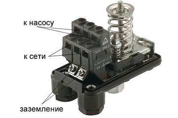
Electrical diagram for connecting the pressure switch to the hydraulic accumulator
Typically, pressure switches for household pumping stations have two groups of contacts, but sometimes you come across models with one.Each group consists of two pairs, and both pairs are closed or opened simultaneously. The contacts in each pair are labeled, for example, “Line/Load” or “Line/Motor”.
In principle, it is not necessary to follow these notations. You can even, for example, connect wires from the network to the “Line” contact of one pair and the “Load” contact of the other.
The main thing is that both wires are not connected to the contacts of one pair - this will lead to a short circuit. The wires leading to the pump motor should be connected to the remaining two contacts. It is desirable that the colors of the braids of the cores connected to one pair match. Before connecting the power cord, make sure it is not plugged into a power outlet.
To connect the grounding conductor (usually it has a yellow-green braid) there is a screw on the relay body, marked with the corresponding symbol.
When connecting the wire from the relay to the pump motor, the blue-braided wire should be connected to the “zero” contact, and the red or black wire to the “phase” contact.
Often, for reliability, the grounding contacts of the pump and the relay are connected to each other, but this is not necessary.

Pressure switch in a water supply system with a deep pump
The cross-sectional area of the wire cores must correspond to the power of the electric motor. For copper wire, the cross-section is selected at the rate of 1 sq. mm for every 8 A of current. To determine the current strength in a single-phase network, it is necessary to divide the power of the electric motor by 220. So, for example, in the circuit of an electric motor with a power of 1.5 kW, a current of 1500/220 = 6.8 A will flow.
It is important not to confuse the values of the diameter of the wire core and its cross-sectional area, since these values can be comparable. For example, the cross-sectional area of a core with a diameter of 1.5 mm is 1.76 square meters. mm.
Please note that the electrical connection must be made only after connecting the pressure switch to the water supply.
 Nowadays, the lack of centralized water supply is no longer such a big problem. A wide variety of pumping equipment allows you to set up an autonomous water supply system without much difficulty. , installation and repair, read on.
You will find a water supply diagram for a private house with a storage tank in the topic.
Video on the topic
Any water supply system, even if assembled perfectly and from the highest quality equipment, may experience operational problems.
The most common problem is a decrease in pressure in the system, due to which water cannot reach the water collection point.
To solve this problem, a device is used that accumulates water and contains compressed air.
It is due to the latter that it works: water is drawn into the battery by a pump, after which it is pushed into the system due to air pressure. This allows the water pressure in the water supply system to always be at the same level.
In order for everything to work without problems, you need to correctly connect the unit to a water source - a well, a well or a water supply system. There are several ways you can do this yourself.
Installation with submersible pump
Diagram for connecting a hydraulic accumulator to a well pump. (Click to enlarge) If the water in the water supply system is taken from a well, the pump pumping water into the accumulator is located underground.
The main feature of this connection scheme is the presence of a check valve in the system.
Thanks to this device, the pumped water will not be able to flow back into the well.
Installation of the check valve is carried out before connecting the remaining elements of the system. It is installed directly on the pump at one end, and the pipeline leading to the hydraulic accumulator is connected to the other.
happens in the following order:
- The depth to which the pump is to be lowered is measured so that it does not reach the bottom of the well or well by about 30 cm. A rope with a load is used for measurement.
- The pump with the connected valve is lowered into the well and secured with a safety rope.
- The pipe from the pump that goes to the surface is connected to through a fitting.
- A hydraulic accumulator, a water supply and a control system are connected to the same fitting. Thus, you will need a five-plug fitting.
Take into account: It is very important to make all connections airtight, for which you can use FUM tape or ordinary tow impregnated with sealant.
Installation with surface pump
If water is pumped into the system from a water supply and submersion of the pump is not required, it can be installed next to the battery itself.
In essence, the connection diagram does not change, but there are some nuances that are important to know.
Before connecting, it is necessary to calculate the operating and minimum pressure. Different systems may require different water pressure, but the standard for small water supply systems with a small number of water intake points is 1.5 atm.
If the system has equipment that requires high pressure, this figure can be increased to 6 atm, but not more, since higher pressure will be dangerous for pipes and their connecting elements.
Determination of critical pressure
Based on the operating value, it is determined what the minimum pressure should be, that is, the indicator at which the pump will start operating.
This value is set using a relay, after which the pressure in the empty accumulator must be measured.
The result should be 0.5 - 1 atm below the critical value. After this, the system is assembled.
Its center, as in the previous case, will be a five-connector fitting, to which the following are connected one after another:
- the accumulator itself;
- a pipe from a pump connected to a water source;
- domestic plumbing;
- relay;
- pressure gauge
Connecting a pressure switch
 In order for the relay to work correctly, it must not only be correctly connected to the fitting, but also configured.
It requires electricity to function.
The top cover is removed from the device, under which there are contacts for connecting the relay to the network and to the pump.
Usually the contacts are signed, but may not have any designations. If you're not sure where something connects, it's best to contact a professional electrician.
Pumping station
 A pumping station is a complex of equipment that includes powerful pumping equipment, a hydraulic accumulator and control devices.
As a result, the connection diagram in this case does not differ from the connection to a conventional pump.
If the station is designed for large volumes of water - for example, in the case of powering several houses from one well - the connection becomes somewhat more complicated.
In this case, several pumps and two fittings are used - the pumping system is connected to one, and the first fitting and the rest of the equipment are connected to the second.
The hydraulic accumulator can be connected not only to a well or water supply system for a water supply system, but also to a heating system. The functions of the unit in this case will be somewhat different, although the principle of operation does not change.
Watch the video in which a specialist explains in detail how to connect a hydraulic accumulator to the water supply system with your own hands: