What machines can be made with your own hands. Homemade cnc milling machine
Difficult to manufacture, in addition to the technical components, it has an electronic device, which can only be installed by a specialist. Contrary to this opinion, the ability to assemble a CNC machine with your own hands is great if you prepare the necessary drawings, diagrams and component materials in advance.
Carrying out preparatory work
When designing a CNC with your own hands at home, you need to decide according to which scheme it will work.
Often, a used one is taken as the basis of a future apparatus.
The drilling machine can be used as the basis for a CNC machine
It will require the replacement of the working head with a milling head.
The greatest difficulty in designing a CNC machine with your own hands is the creation of a device with which the working tool moves in three planes.
Partially solve the problem will help carriages taken from a conventional printer. The tool will be able to move in both planes. It is better to choose carriages for a CNC machine from a printer that has large dimensions.
Such a scheme allows you to later connect to the machine control. The downside is that the CNC milling machine only works with wood, plastic products, thin metal products. This is due to the fact that the printer carriages do not have the necessary rigidity.
Attention must be paid to the engine of the future unit. Its role is reduced to the movement of the working tool. The quality of work and the possibility of performing milling operations depend on this.
A good option for a homemade CNC router is a stepper motor.

An alternative to such an engine is an electric motor, previously improved and adjusted to the standards of the device.
Anyone using a stepper motor allows you to not use a screw drive, this does not affect the capabilities of such a wood CNC in any way. It is recommended to use toothed belts for milling on such a unit. Unlike standard belts, they do not slip on pulleys.
It is required to correctly design the milling cutter of the future machine, for this you will need detailed drawings.
Materials and tools required for assembly
The general set of materials for a CNC machine includes:
- cable 14–19 m long;
- processing wood;
- cutter chuck;
- a frequency converter having the same power as the spindle;
- bearings;
- control board;
- water pump;
- cooling hose;
- three stepping motors for three axes of movement of the structure;
- bolts;
- protective cable;
- screws;
- plywood, chipboard, wood slab or metal structure to choose from as the body of the future apparatus;
- soft clutch.

It is recommended that when making your own hands, use a spindle with coolant. This will allow you not to turn it off every 10 minutes to cool down. A home-made CNC machine is suitable for work, its power is at least 1.2 kW. The best option would be a device with a power of 2 kW.
The set of tools required for the manufacture of the unit includes:
- hammers;
- electrical tape;
- assembly keys;
- glue;
- screwdriver
- soldering iron, sealant;
- grinder, it is often replaced with a hacksaw;
- pliers, welding machine, scissors, pliers.
A simple CNC do-it-yourself machine
Procedure for assembling the machine
Homemade CNC milling machine is assembled according to the scheme:
- production of drawings and diagrams of the device indicating the electrical system;
- purchase of materials containing a future home-made CNC machine;
- installation of a bed, engines, a working surface, a portal, a spindle will be mounted on it;
- portal installation;
- setting the Z axis;
- fixing the working surface;
- spindle installation;
- installation of a water-cooling system;
- installation of the electrical system;
- connection of the board, with its help the device is controlled;
- software setup;
- start-up of the unit.
The basis for the bed is a material made of aluminum.

The frame must be made from aluminum
Profiles of this metal are selected with a section of 41 * 81 mm with a plate thickness of 11 mm. The body of the bed itself is connected using aluminum corners.
The installation of the portal will determine how thick the product can be processed by the CNC machine. Especially if it's handmade. The higher the portal, the thicker the product it can process. It is important not to install it too high, as this design will be less durable and reliable. The portal moves along the X axis and carries the spindle on itself.
An aluminum profile is used as a material for the working surface of the unit. Often take a profile with T-slots. For home use, they accept, its thickness is at least 17 mm.
After the frame of the device is ready, proceed to install the spindle. It is important to install it vertically, since in the future it will need to be adjusted, this is done to fix the required angle.
To install the electrical system, the presence of the following components is required:
- power unit;
- a computer;
- stepper motor;
- pay;
- stop button;
- motor drivers.

The system requires an LPT port. In addition, it is installed that controls the operation of the apparatus and allows you to answer the question of how to perform this or that operation. The control is connected via motors to the milling machine itself.
After the electronics is installed on the machine, you will need to download the drivers and programs necessary for operation.
Common Build Mistakes
A common mistake when assembling a CNC machine is the lack of a drawing, but the assembly is carried out according to it. As a result, there are omissions in the design and installation of apparatus structures.
Often the incorrect operation of the machine is associated with incorrectly selected frequency converter and spindle.

For the correct operation of the machine, it is necessary to choose the right spindle
In many cases, stepper motors do not receive proper power, so a special separate power supply must be selected for them.
It must be taken into account that a properly installed wiring diagram and software allows you to perform numerous operations of various levels of complexity on the device. Do-it-yourself CNC machine can be done by a middle-level master, the design of the unit has a number of features, but using the drawings it is not difficult to assemble the parts.
It is easy to work with a CNC, compiled with your own hands, you need to study the informative base, conduct a series of training work and analyze the condition of the unit and parts. Do not rush, pull moving parts or open the CNC.
Axle arrangementX, Y, Zdesktop CNC milling and engraving machine:
The Z axis moves the tool (milling cutter) vertically (up and down)
Axis X - moves the carriage Z in the transverse direction (left-right).
Y-axis - moves the movable table (back and forth).
The device of the milling and engraving machine can be found
The composition of the set of CNC machine Modelist2020 and Modelist3030
I A set of milled parts made of 12mm plywood for self-assembly
A set of milled parts for the assembly of a CNC machine with a sliding table consists of:
1) CNC router gantry legs
2) a set of CNC milled parts to assemble the Z axis
3) A set of CNC milled parts to assemble the sliding table
4) a set of milled CNC machine parts for assembling stepper motor supports and spindle mounting
II Set of milling machine mechanics includes:
1. coupling for connecting the stepper motor shaft with the lead screw of the machine - (3 pcs.). The size of the coupling for the Modelist2030 machine with NEMA17 stepper motors is 5x5mm. For Modelist3030 machine with Nema23 stepper motors - 6.35x8mm
2. steel linear guides for CNC machine Modelist3030:
16mm (4pcs) for X and Y axes,
12mm(2pcs) for Z axis
For CNC machine Modelist2020, the diameter of the linear movement guides:
12mm(8pcs) for X, Y and Z axes.
3. linear rolling bearings for milling machine Modelist3030:
Linear bearings LM16UU (8pcs) for X and Y axes,
Linear bearings LM12UU for Z axis.
For CNC milling machine Modelist2020
Linear bearings LM12UU (12pcs) for X, Y and Z axes.
4. lead screws for the milling machine Modelist2020 - M12 (pitch 1.75mm) - (3pcs) with processing under d=5mm from one end and under d=8mm from the other.
For milling machine Modelist3030 - TR12x3 trapezoidal screws (pitch 3mm) - (3 pcs.) with end processing under d=8mm.
5. radial bearings for fastening the lead screws - (4pcs) one bearing in an aluminum block for the Z axis.
6. running nuts made of graphite-filled caprolon for the X, Y and Z axes (- 3 pcs.)
III CNC milling machine electronics set:
1. For CNC machine Modelist2020: NEMA17 stepper motors 17HS8401(size 42x48mm, torque 52N.cm , current 1.8A, phase resistance 1.8Ω, inductance 3.2mH, shaft diameter 5mm)- 3 pcs.
For CNC machine Modelist3030: stepper motors 23HS5630 (size 57x56mm, torque 12.6kg*cm, current 3.0A, phase resistance 0.8Ω, inductance 2.4mH, shaft diameter 6.35mm)- 3 pcs.
2. CNC stepper motor controller based on specialized Toshiba TV6560 microstepping drivers in a closed aluminum case
3. power supply 24 V 6.5 A for CNC machine Modelist2020 and 24V 10.5A for CNC machine Modelist3030
4. set of connecting wires
The assembly sequence of the CNC milling machine with a movable table.
The linear movement system of any machine tool consists of two parts: a linear bushing is an element that moves and a fixed element of the system - a linear guide or shaft (linear support). Linear bearings can be of different types: bushing, split bushing, aluminum bushing for easy mounting, ball carriage, roller carriage, the main function of which is to bear the load, ensuring stable and accurate movement. The use of linear bearings (rolling friction) instead of sliding sleeves can significantly reduce friction and use the full power of stepper motors for useful cutting work.
Picture 1
1 Lubricate the linear bearings of the system linear movement of the milling machine with special grease (you can use Litol-24 (sold in auto parts stores)).
2 Assembling the Z axis of the CNC milling machine.
The assembly of the Z axis is described in the instruction ""
3 CNC milling table assembly, Y axis
3.1 Details for assembling the portal, figure 2.
1) a set of milled parts
4) lead screws for the milling machine Modelist2030 - M12 (pitch 1.75mm) with end machining for d=8mm and d=5mm

Figure 2. Details of the portal milling desktop CNC machine
3.2 Press in the linear bearings and insert the linear bearing holders into the milled grooves, Figure 2. Insert the linear guides into the linear ball bearings.

Figure 2 Assembling the table of a desktop CNC milling machine
3.3 The linear bearing holders are driven into the grooves of the sliding table part. The thorn-and-groove connection provides excellent rigidity of the knot, all parts of this knot are made of 18mm plywood. Additionally, by tightening the parts with a bolted connection, we will ensure a long and reliable service life, for this, through the existing hole in the plate, which serves as a guide for the drill, we drill a hole in the end face of the linear bearing holder, as shown in Figure 3, a drill with a diameter of 4mm.

Figure 3 Drilling mounting holes.
3.4 We impose the table itself and, through the existing holes, we fasten it with the help of M4x55 screws from the kit, Figure 4 and 5.

Figure 4 Mounting the slide table bearings.

Figure 5 Mounting the slide table bearings.
3.5 Press the thrust bearings into the details of the table frame. Insert the lead screw with lead nut made of graphite-filled caprolon into the thrust bearings and linear guides into the grooves of the frame elements, Figure 6.

Figure 6. Assembly of the sliding table.
Fasten the frame elements with screws from the kit. For fastening from the sides, use screws 3x25mm, Figure 7. Before screwing in the screws, be sure to drill with a 2mm drill to avoid delamination of the plywood.
If the lead screw is not clamped by the parts of the base of the movable table and there is play of the screw along the axis in the support bearings, use a washer with a diameter of 8 mm, Figure 6.

Figure 7. Assembly of the frame of the desktop machine.
3.6 Center the drive nut between the linear bearings and make holes for the screws with a 2mm drill, Figure 8, then use the 3x20 screws from the kit to secure the drive nut. When drilling, be sure to use a stop under the spindle nut so as not to bend the spindle. .

Figure 8. Fastening the running nut.
4 Assembling the portal of the machine.
For assembly you will need:
1) a set of milled parts for assembling the sliding table
2) steel linear guides with a diameter of 16mm (2pcs)
3) linear bearing LM16UU(4pcs)
4) lead screws for the milling machine Modelist2030 - M12 (pitch 1.75mm) with end machining under d=8mm and d=5mm.
For milling machine Modelist3030 - TR12x3 trapezoidal screws (pitch 3mm) with end machining under d=8mm.
5. radial bearings for fastening the lead screws - (2 pcs.)
6. running nut made of graphite-filled caprolon - (- 1 pc.)
4.1 Fasten the sidewall of the portal, Figure 9.

Figure 9. Machine portal assembly.
4.2 Insert the lead screw with nut into the frame of the Z-axis carriage, figure 10.
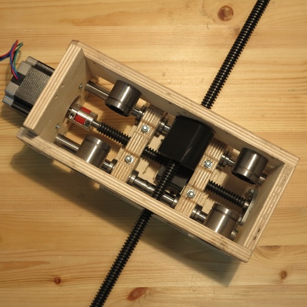
Figure 10 Lead screw installation.
4.3 Insert linear guides, figure 11.

Figure 19 Fastening the lead screw "in the thrust".
4.4 Fasten the second side of the portal, Figure 11.

Figure 11. Installing the second side of the portal
If the lead screw is not clamped by the parts of the base of the movable table and there is play along the axis, use a washer with a diameter of 8mm.
4.5 Install and secure the rear wall of the carriage Z, Figure 12.

Figure 12. Fastening the rear wall of the Z carriage.
4.6 Fasten the caprolon running nut with 3x20 screws from the kit, Figure 13.

Figure 13. Attaching the X Axis Lead Nut.
4.7 Fasten the rear wall of the portal, Figure 14, using 3x25 screws from the kit. 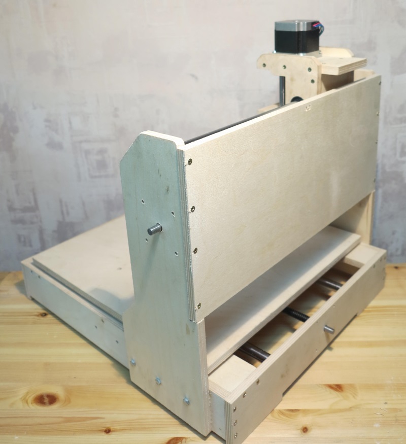
Figure 14. Fastening the rear wall of the portal.
5 Installation of stepper motors.
To install stepper motors, use the fasteners from the set of milled parts of the CNC machine to assemble the Nema23 stepper motor supports for the Modelist3030 milling machine.

Figure 15. Installation of stepper motors.
Install 5x8mm couplings to connect the motor shaft to the lead screw. Fasten the stepper motors to the machine, for fastening use the M4x55 screw from the kit, Figure 15.
6 Attach the controller to the back of the router, and connect the motor terminals to it.
7 Installing the router.
The router is fastened by the neck of the tool or the body. The standard diameter of the neck of household routers is 43mm. Spindle diameter 300W - 52mm, mounted on the body. For installation, assemble the router mount, fastening details in Figure 16. Use the 3x30mm screw from the kit.
Figure 16 Spindle mount 43mm
Figure 17 CNC Mounted Spindle
When installing Dremel similar tools (engravers), in addition, you will need to additionally fasten the engraver body to the Z carriage with a clamp, Figure 18.

Figure 18 Mounting the engraver on the milling machine.
It is possible to install a nozzle for connecting a vacuum cleaner
This is my first CNC machine assembled with my own hands from available materials. The cost of the machine is about $170.
I dreamed of assembling a CNC machine for a long time. Basically, I need it for cutting plywood and plastic, cutting some details for modeling, homemade and other machines. My hands itched to assemble the machine for almost two years, during which time I collected parts, electronics and knowledge.
The machine is budget, its cost is minimal. Further, I will use words that may seem very scary to an ordinary person and this can scare away from self-building a machine, but in fact it is all very simple and easy to master in a few days.
Electronics assembled on Arduino + GRBL firmware
The mechanics are the simplest, plywood frame 10mm + screws and bolts 8mm, linear guides from a metal corner 25 * 25 * 3 mm + bearings 8 * 7 * 22 mm. The Z axis runs on an M8 stud and the X and Y axes on T2.5 belts.
The CNC spindle is homemade, assembled from a brushless motor and a collet clamp + toothed belt drive. It should be noted that the spindle motor is powered by a 24 volt main power supply. The specifications indicate that the motor is 80 amps, but in reality it consumes 4 amps under serious load. I can’t explain why this is happening, but the motor works fine and does its job.

Initially, the Z axis was on self-made linear guides from angles and bearings, later I redid it, pictures and description below.

The working space is about 45 cm in X and 33 cm in Y, 4 cm in Z. Considering the first experience, I will make the next machine with large dimensions and I will put two motors on the X axis, one from each side. This is due to the large shoulder and the load on it when work is carried out at the maximum distance along the Y axis. Now there is one motor and this leads to distortion of the parts, the circle turns out to be a little elliptical due to the resulting deflection of the carriage along X.

The native bearings of the motor quickly loosened up, because they were not designed for lateral load, but it is serious here. Therefore, I installed two large bearings with a diameter of 8 mm on top and bottom on the axle, this should have been done immediately, now there is vibration because of this.

Here in the photo you can see that the Z-axis is already on other linear guides, the description will be below.


The guides themselves have a very simple design, I somehow accidentally found it on Youtube. Then this design seemed to me ideal from all sides, a minimum of effort, a minimum of parts, simple assembly. But as practice has shown, these guides do not work for long. The photo shows what kind of groove formed on the Z axis after a week of my test runs of the CNC machine.

I replaced the homemade z-axis rails with furniture ones that cost less than a dollar for two. I shortened them, left a stroke of 8 cm. There are still old guides on the X and Y axes, I won’t change them yet, I plan to cut parts for a new machine on this machine, then I’ll just disassemble this one.


A few words about cutters. I have never worked with CNC and have very little experience in milling. I bought several cutters in China, all have 3 and 4 grooves, later I realized that these cutters are good for metal, other cutters are needed for milling plywood. While new cutters cover the distance from China to Belarus, I am trying to work with what I have.
The photo shows how a 4 mm cutter burned on 10 mm birch plywood, I still didn’t understand why, the plywood was clean, and on the cutter there was soot similar to pine resin.

Further on the photo there is a 2 mm four-start cutter after an attempt to mill plastic. This piece of molten plastic was then very poorly removed, biting off a little bit with wire cutters. Even at low speeds, the cutter still gets stuck, 4 grooves are clearly for metal :)

The other day my uncle had a birthday, on this occasion I decided to make a gift on my toy :)
As a gift, he made a full house of plywood. First of all, I tried to mill on foam plastic in order to check the program and not spoil the plywood.


Due to backlashes and deflections, the horseshoe was cut out only from the seventh time.


In total, this full house (in its pure form) was milled for about 5 hours + a lot of time for what was spoiled.

Somehow I published an article about the key holder, below in the photo is the same key holder, but already cut on a CNC machine. Minimum effort, maximum accuracy. Due to the backlash, the accuracy is certainly not the maximum, but I will make the second machine more rigid.


And I also cut gears out of plywood on a CNC machine, it's much more convenient and faster than cutting with a jigsaw with my own hands.
Later I also cut out square gears from plywood, they actually spin :)
The results are positive. Now I will develop a new machine, I will cut out parts already on this machine, manual labor is practically reduced to assembly.
You need to master the cutting of plastic, because work on a homemade robot vacuum cleaner got up. Actually, the robot also pushed me to create my own CNC. For the robot, I will cut gears and other parts from plastic.
Update: Now I buy straight cutters with two edges (3.175*2.0*12 mm), they cut without severe scuffing on both sides of the plywood.
Knowing that a CNC milling machine is considered sophisticated technical and electronic equipment, many craftsmen think that it simply cannot be done by hand.
However, this opinion is not true: you can make such a device with your own hands, but for this you need to have not only its complete drawing, but also a set of certain tools and suitable components.
DIY CNC machine (drawings)
When deciding to create a homemade special CNC machine, remember that this can take a lot of time. In addition, you will need a lot of money.
To make a milling machine that is equipped with a CNC system, you can use 2 methods: purchase a ready-made set of specially selected parts from which such equipment is assembled, or find all the components and independently assemble a device that fully meets all your requirements.
Preparation for work
If you planned to make a CNC machine yourself without using a ready-made kit, then the first thing you will need to do is stop at special scheme, on which such a mini-device will work.

Equipment assembly
The basis of the assembled milling equipment can be a rectangular beam, which must be firmly fixed on the rails.
 The supporting structure of the equipment must have high rigidity. When installing it, it is better not to use welded joints, but to attach all parts only with screws.
In the milling equipment that you will assemble yourself, a mechanism must be provided that will ensure that the working device moves in a vertical direction. It is best to take a screw gear for it, the rotation of which will be transmitted using a toothed belt.
The main part of the machine
An important part of such a machine is its vertical axis, which for a home-made device can be made from an aluminum plate. Remember to the dimensions of such an axis were precisely matched to the dimensions of the device being created.
For most home craftsmen, the manufacture of such an assembly as a do-it-yourself CNC milling machine is something at the level of a fantastic plot, because such machines and mechanisms are complex in design, constructive and electronic understanding of the device.
However, having at hand the necessary documentation, as well as the required materials, fixtures, it is quite possible to make a mini-milling home-made machine equipped with a CNC with your own hands.
This mechanism is distinguished by the accuracy of the processing performed, the ease of control of mechanical and technological processes, as well as excellent indicators of productivity and product quality.
Principle of operation
Innovative computer-controlled block milling machines designed for complex patterns on semi-finished products. The design must have an electronic component. Together, this will allow you to automate work processes to the maximum.
To model milling mechanisms, you first need to familiarize yourself with the fundamental elements. The role of the actuating element is a cutter, which is mounted in a spindle located on the shaft of an electric motor. This part is fixed on the base. It is capable of moving in two coordinate axes: X and Y. Design and install a support table to fix the workpieces.
The electric adjustment unit articulates with the electric propulsion motors. They will ensure the movement of the carriage relative to the workpieces or semi-finished products being processed. Using a similar technology, a 3D graphic image is made on wooden planes.
The sequence of work performed by this CNC mechanism:
- Writing a working program, due to which the movements of the working body will be performed. For this procedure, it is best to use specialized electronic systems designed to adapt in "handicraft" copies.
- Mounting semi-finished products on the table.
- Software output to the CNC.
- Starting mechanisms, controlling the passage of automatic manipulations of equipment.
To get the maximum level of automation in 3D mode, correctly complete the diagram and label certain components. Experts strongly advise to initially study production copies before starting to build a milling machine with your own hands.
Scheme and drawing

Scheme of a CNC milling machine
The most critical phase in the manufacture of a home-made analogue is the search for the optimal course of equipment manufacturing. It directly depends on the overall characteristics of the workpieces being processed and the need to achieve a certain quality in processing.
For the need to obtain all the necessary functions of the equipment, the best option is to make a mini-milling machine with your own hands. Thus, you will be sure not only of the assembly and its quality, but also of the technological properties, it will be known in advance how to maintain it.
![]()
Transmission components
The most successful option is to design 2 carriages moving along perpendicular axes X and Y. It is better to use polished metal rods as a frame. Mobile mobile carriages are “dressed” on them. For the correct manufacture of the transmission, prepare stepper motors, as well as a set of screws.
For improved automation of the workflows of CNC milling machines, designed by oneself, it is required to immediately complete the electronic component to the smallest detail. It is divided into the following components:
- used to conduct electrical energy to stepper motors and power the controller chip. Running is considered modification 12v 3A;
- its purpose is to give commands to the engines. For the correct execution of all specified operations of a CNC milling machine, it will be enough to use a simple scheme to monitor the performance of 3 engines;
- drivers (software). It is also an element for adjusting the movable mechanism.
Video: do-it-yourself CNC milling machine.
Accessories for a homemade milling machine

The next, and crucial step in the construction of milling equipment is the selection of components for building a home-made unit. The best way out of this situation is the use of improvised parts and devices. It is possible to take solid wood species (beech, hornbeam), aluminum / steel or organic glass as the basis for desktop copies of 3D machines.
For the normal operation of the complex as a whole, the development of the design of calipers is required. At the moment of their movement, oscillations are not unacceptable, this will cause incorrect milling. Therefore, before assembly, the components are checked for reliable operation.
Practical tips for choosing the components of a CNC milling machine:
- guides - well-polished steel bars Ø12 mm are used. The length of the X axis is about 200 mm, Y - 100 mm;
- caliper mechanism, optimal material - textolite. Standard site dimensions are 30×100×50 mm;
- stepper motors - engineering experts advise using samples from a 24v, 5A printing device. They have a fairly significant power;
- a block for fixing the working body, it can also be built using textolite. The configuration is directly dependent on the tool that is available.
The procedure for building CNC milling equipment
After completing the selection of all the necessary components, you can completely easily build an oversized milling mechanism equipped with CNC with your own hands. Before proceeding with the direct design, we once again check the components, control their parameters and workmanship. This will further help to avoid premature failure of the mechanism chain.
For reliable fixation of equipment components, specialized fasteners are used. Their design and execution directly depend on the future scheme.
The list of necessary steps to assemble a small CNC equipment to perform the milling process:
- Mounting the guide axles of the support element, fixing on the extreme parts of the machine.
- Grinding calipers. It is required to move along the guides until a smooth movement is formed.
- Tightening the screws to fix the support device.
- Fastening components to the base of the working mechanism.
- Mounting lead screws and couplings.
- Installation of marching motors. They are attached to the coupling bolts.
Electronic components are located in a self-contained cabinet. This ensures the minimization of failures in performance in the process of carrying out technological operations with a milling cutter. The plane for mounting the working machine must be without drops, because the design does not provide for leveling screws.
After completing the above, proceed to perform trial tests. First you need to install a light program to perform milling. In the process of work, it is necessary to continuously check all passes of the working body (cutter). Parameters that are subject to constant control: the depth and width of processing. This applies especially to 3D processing.
Thus, referring to the information written above, making milling equipment with your own hands provides a whole list of advantages over conventional purchased counterparts. Firstly, this design will be suitable for the expected volumes and types of work, secondly, maintainability is ensured, since it is built from improvised materials and fixtures, and, thirdly, this equipment option is inexpensive.
Having experience in designing such equipment, further repairs will not take much time, downtime will be reduced to a minimum. Such equipment can be useful to your neighbors in their summer cottage to carry out their own repairs. By renting such equipment, you will help your close friend in work, count on his help in the future.
Having dealt with the design and functional features of milling machines, as well as the load that will fall on it, you can safely start manufacturing it, based on the practical information given along the text. Design and complete tasks without any problems.
Video: homemade CNC wood milling machine.