How to increase the resistance of a variable resistor. Parallel connection of variable and constant resistors
used to increase resistance. Those. when resistors are connected in series, the total resistance is equal to the sum of the resistances of each resistor. For example, if resistors R1 and R2 are connected in series, their total resistance is calculated using the formula:
R = R1 + R2 .
This is also true for a larger number of resistors connected in series:
R = R1 + R2 + R3 + R4 + ... + Rn .
Chain of series connected resistors will always have resistance more than any resistor in this circuit.
When resistors are connected in series, a change in the resistance of any resistor from this circuit entails both a change in the resistance of the entire circuit and a change in the current in this circuit.
Parallel connection of resistors (formula)

It is necessary to reduce the total resistance and, as an option, to increase the power of several resistors compared to one.
Parallel resistance calculation
Parallel resistance calculation two parallel connected resistors R1 and R2 are made according to the following formula:Connecting three or more resistors in parallel requires a more complex formula to calculate the total resistance:
Resistance of parallel resistors
| 1 | = | 1 | + | 1 | + | 1 | + ... |
| R | R1 | R2 | R3 |
As you can see, calculate resistance of two parallel resistors much more convenient.
The resistance of parallel connected resistors will always be less than that of any of these resistors.
Often used in cases where higher power resistance is needed. To do this, as a rule, resistors with the same power and the same resistance are used. The total power, in this case, is calculated by multiplying the power of one resistor by the number of resistors connected in parallel.
For example: ten resistors with a nominal value of 1 KOhm and a power of 1 W each, connected in parallel, will have a total resistance of 100 Ohms and a power of 10 W.
When connected in series, the power of the resistors also adds up. Those. in the same example, but with a series connection, the total resistance will be 10 KOhm and the power will be 10 W.
In electronic equipment circuits, one of the most frequently encountered elements is resistance; its other name is resistance. It has a number of characteristics, among which is power. In this article we will talk about resistors, what to do if you do not have an element suitable for the power, and why they burn out.
Resistor characteristics
1. The main parameter of a resistor is the nominal resistance.
2. The second parameter by which it is selected is the maximum (or maximum) power dissipation.
3. Temperature coefficient of resistance - describes how much the resistance changes when its temperature changes by 1 degree Celsius.
4. Permissible deviation from the nominal value. Typically, the spread of resistor parameters from one declared is within 5-10%, it depends on GOST or specifications according to which it is manufactured; there are also precise resistors with a deviation of up to 1%, which usually cost more.
5. The maximum operating voltage depends on the design of the element; in household electrical appliances with a supply voltage of 220V, almost any resistors can be used.
6. Noise characteristics.
7. Maximum ambient temperature. This is the temperature that can occur when the maximum power dissipation of the resistor itself is reached. We'll talk more about this later.
8. Moisture and heat resistance.
There are two more characteristics that beginners most often do not know about:
At low frequencies (for example, within the audio range up to 20 kHz), they do not significantly affect the operation of the circuit. In high-frequency devices, with operating frequencies of hundreds of thousands of hertz and above, even the location of the tracks on the board and their shape make a significant impact.

From the physics course, many people perfectly remember the power formula for electricity, this is: P=U*I
It follows that it linearly depends on current and voltage. The current through the resistor depends on its resistance and the voltage applied to it, that is:
The voltage drop across a resistor (how much voltage remains at its terminals from the voltage applied to the circuit in which it is installed) also depends on the current and resistance:
Now let’s explain in simple words what the power of a resistor is and where it is allocated.
Any metal has its own resistivity, this is a value that depends on the structure of that metal itself. When charge carriers (in our case, electrons) flow through a conductor under the influence of an electric current, they collide with the particles that make up the metal.
As a result of these collisions, the flow of current is hampered. To put it very generally, it turns out that the denser the metal structure, the more difficult it is for current to flow (the greater the resistance).
The picture shows an example of a crystal lattice, for clarity.
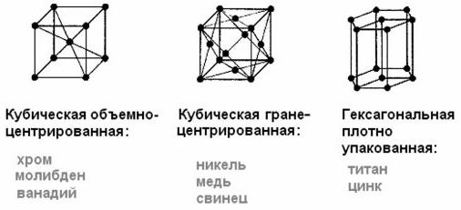
These collisions generate heat. Can you think of it as if you were walking through a crowd (lots of resistance) where you were also being pushed, or if you were walking down an empty corridor where you would sweat more?
The same thing happens with metal. Power is released as heat. In some cases, this is bad because it reduces the efficiency of the device. In other situations this is a useful property, for example. In incandescent lamps, due to its resistance, the spiral heats up to a bright glow.
But how does this apply to resistors?
The fact is that resistors are used to limit the current when powering any devices or circuit elements, or to set operating modes for semiconductor devices. We described this. From the formula above it will become clear that the current decreases due to a decrease in voltage. Excess voltage can be said to be burned in the form of heat on a resistor, and the power is calculated using the same formula as the total power:
Here U is the number of volts "burned" across the resistor, and I is the current that flows through it.
The heat generated by a resistor is explained by the Joule-Lenz law, which relates the amount of heat generated to current and resistance. The greater the first or second, the more heat will be released.
To make it convenient, two more formulas are derived from this formula by substituting Ohm’s law for a section of the chain.
To determine power through the applied voltage to a resistor:
To determine the power through the current flowing through a resistor:
A little practice
For example, let's determine how much power is allocated to a 1 Ohm resistor connected to a 12V voltage source.
First, let's calculate the current in the circuit:
Now the power according to the classic formula:
P=12*12=144 W.
One step in calculations can be avoided if you use the above formulas, let's check it:
P=12^2/1=144/1=144 W.
Everything fits together. The resistor will generate heat with a power of 144W. These are conditional values taken as an example. In practice, you will not find such resistors in electronic equipment, with the exception of large resistances for regulating DC motors or starting powerful synchronous machines in asynchronous mode.
What types of resistors are there and how they are indicated in the diagram
The range of resistor powers is standard: 0.05 (0.62) - 0.125 - 0.25 - 0.5 - 1 - 2 - 5
These are typical values of common resistors; there are also larger values or other values. But this series is the most common. When assembling electronics, an electrical circuit diagram is used, starting with the serial number of the elements. It is less common to indicate the nominal resistance, and even less often the nominal resistance and power are indicated.
To quickly determine the power of the resistor in the diagram, the corresponding UGO (symbolic graphic symbols) according to GOST were introduced. The appearance of such designations and their interpretation are presented in the table below.

In general, this data, as well as the name of the specific type of resistor, is indicated in the list of elements, and the permitted tolerance in % is also indicated there.
Externally, they differ in size; the more powerful the element, the larger its size. A larger size increases the area of heat exchange between the resistor and the environment. Therefore, the heat that is released when current passes through the resistance is transferred more quickly to the air (if the environment is air).
This means that the resistor can heat up with greater power (release a certain amount of heat per unit time). When the temperature of the resistance reaches a certain level, first the outer layer with the marking begins to burn out, then the resistive layer (film, wire or something else) burns out.
To give you an idea of how hot a resistor can get, take a look at the heating of the coil of a disassembled powerful resistor (more than 5 W) in a ceramic case.

The characteristics included such a parameter as the permissible ambient temperature. It is indicated for the correct selection of the element. The fact is that since the power of the resistor is limited by its ability to transfer heat and, at the same time, not overheat, but to transfer heat, i.e. When cooling the element by convection or forced air flow, there should be as large a difference as possible between the temperatures of the element and the environment.
Therefore, if it is too hot around the element, it will heat up faster and burn out, even if the electrical power on it is below the maximum dissipated. Normal temperature is 20-25 degrees Celsius.
Continuing this topic:
What to do if there is no resistor of the required power?
A common problem for radio amateurs is the lack of a resistor of the required power. If you have resistors that are more powerful than you need, there is nothing wrong with that, you can install them without hesitation. If only it fits in size. If all the available resistors are less powerful than needed, this is already a problem.
In fact, solving this issue is quite simple. Remember the laws of series and parallel connection of resistors.
1. When resistors are connected in series, the sum of the voltage drops across the entire chain is equal to the sum of the drops across each of them. And the current flowing through each resistor is equal to the total current, i.e. in a circuit of series-connected elements, ONE current flows, but the voltages applied to each of them are DIFFERENT, determined by Ohm’s law for a section of the circuit (see above) Utot = U1 + U2 + U3
2. When resistors are connected in parallel, the voltage drop across all is equal, and the current flowing in each of the branches is inversely proportional to the resistance of the branch. The total current of a chain of parallel-connected resistors is equal to the sum of the currents of each of the branches.
This picture shows all of the above in an easy to remember form.

So, just as when connecting resistors in series, the voltage on each of them will decrease, and when connecting resistors in parallel, the current will decrease, then if P = U*I
The power output from each will be reduced accordingly.
Therefore, if you do not have a 100 ohm 1 W resistor, it can almost always be replaced with 2 50 ohm and 0.5 W resistors connected in series, or 2 200 ohm and 0.5 W resistors connected in parallel.

I wrote “ALMOST ALWAYS” for a reason. The fact is that not all resistors tolerate shock currents equally well; in some circuits, for example those associated with charging large capacitors, at the initial moment of time they tolerate a large shock load, which can damage its resistive layer. Such connections need to be checked in practice or through long calculations and reading technical documentation and specifications for resistors, which almost no one ever does.

Conclusion
The power of a resistor is a value no less important than its nominal resistance. If you do not pay attention to the selection of resistances needed for power, then they will burn out and get very hot, which is bad in any circuit.
When repairing equipment, especially Chinese equipment, do not under any circumstances try to install resistors of lower power; it is better to supply it with a reserve, if it is possible to fit it within the dimensions on the board.
For stable and reliable operation of a radio-electronic device, it is necessary to select the power with a margin of at least half of the expected value, or better yet, 2 times more. This means that if, according to calculations, 0.9-1 W is released on the resistor, then the power of the resistor or their assembly should be no less than 1.5-2 W.
It seems like a simple detail, what could be complicated here? But no! There are a couple of tricks to using this thing. Structurally, the variable resistor is designed in the same way as it is shown in the diagram - a strip of material with resistance, contacts are soldered to the edges, but there is also a movable third terminal that can take any position on this strip, dividing the resistance into parts. It can serve as both an overclockable voltage divider (potentiometer) and a variable resistor - if you just need to change the resistance.
The trick is constructive:
Let's say we need to make a variable resistance. We need two outputs, but the device has three. It seems that the obvious thing suggests itself - do not use one extreme conclusion, but use only the middle and second extreme. Bad idea! Why? It’s just that when moving along the strip, the moving contact can jump, tremble and otherwise lose contact with the surface. In this case, the resistance of our variable resistor becomes infinite, causing interference during tuning, sparking and burning out of the graphite track of the resistor, and taking the device being tuned out of the permissible tuning mode, which can be fatal.
Solution? Connect the extreme terminal to the middle one. In this case, the worst thing that awaits the device is a short-term appearance of maximum resistance, but not a break.
Fighting limit values.
If a variable resistor regulates the current, for example, powering an LED, then when brought to the extreme position we can bring the resistance to zero, and this is essentially the absence of a resistor - the LED will char and burn out. So you need to introduce an additional resistor that sets the minimum allowable resistance. Moreover, there are two solutions here - the obvious and the beautiful :) The obvious is understandable in its simplicity, but the beautiful is remarkable in that we do not change the maximum possible resistance, given the impossibility of bringing the engine to zero. When the engine is in the highest position, the resistance will be equal to (R1*R2)/(R1+R2)- minimal resistance. And at the extreme bottom it will be equal R1- the one we calculated, and there is no need to make allowances for the additional resistor. It's beautiful! :)
If you need to insert a limitation on both sides, then simply insert a constant resistor at the top and bottom. Simple and effective. At the same time, you can get an increase in accuracy, according to the principle given below.
Sometimes it is necessary to adjust the resistance by many kOhms, but adjust it just a little - by a fraction of a percent. In order not to use a screwdriver to catch these microdegrees of rotation of the engine on a large resistor, they install two variables. One for a large resistance, and the second for a small one, equal to the value of the intended adjustment. As a result, we have two twisters - one " Rough"second" Exactly“We set the large one to an approximate value, and then with the small one we bring it to condition.
For any radio amateur, a resistor is a part that is needed in almost every, even the simplest circuit. In a trivial situation, the resistance is a coil of wire that does not conduct electric current well; constantan is often used as a metal.
For a variable or constant resistor, for experimental purposes, you can use graphite, the rod of which is located inside a simple pencil. It has good electrical conductivity. Therefore, for a homemade resistor you need a thin layer of it, which can be applied to paper and combine the required resistance of up to several hundred kilo-ohms.
Based on the properties of graphite, we will build a working model of a resistor on paper. In this case, we will proceed from simple arithmetic: the longer the conductor, the greater its electrical resistance.
In the photo below the indicator shows in megaohms.
The display shows that a strip of graphite, which is 2 times longer, has, accordingly, 2 times the resistance index. Please note that the width of the stripes is the same.

A wide conductor has less resistance.

A strip of graphite applied to paper can easily be turned into an experimental variable resistor, or, otherwise, let’s call it a rheostat.

This idea is perfect for physics lessons. Material used from the site samodelnie.ru
According to GOST, resistors whose resistance cannot be changed during operation are called constant resistors. Resistors, with the help of which various adjustments are made in the equipment by changing their resistance, are called variable resistors (among radio amateurs, their old, incorrect name is often still used - potentiometers). Resistors whose resistance is changed only during the process of setting up (adjusting) the equipment using a tool, such as a screwdriver, are called tuning resistors.
In addition, various non-wire nonlinear resistors are used in electronic equipment:
varistors, the resistance of which varies greatly depending on the voltage applied to them;
thermistors, or thermistors, the resistance of which varies within significant limits with changes in temperature and voltage;
photoresistors (photocells with an internal photoelectric effect) are devices whose resistance decreases under the influence of light or other radiation (this resistance also depends on the applied voltage).
Fixed resistors for wide use are manufactured with a deviation from the nominal value (tolerance) of ±5, ±10, ±20%. Deviations ±5 and ±10% are included in the Map
resistor identification and are indicated next to the value. On small-sized resistors, instead of the ±5% designation, the number I is indicated (which indicates the first accuracy class), and instead of ±10%, the number II (the second accuracy class). Resistors that do not have such designations have a deviation from. nominal value can be up to ±20%.
The accuracy class characterizes only a certain property of the resistor. But one should not at all conclude that a device that uses resistors of only the first accuracy class will work better than a device that does not adhere to this principle. You shouldn't even strive for this. The accuracy class only indicates the possibility of using a resistor in certain circuits or devices.
Thus, fixed resistors used in measuring equipment must have a small resistance deviation from the nominal value. Resistors of the ULI, BPL, MGP types used in such equipment are manufactured with a deviation from the nominal value of ±0.1; ±0.2; ±0.5; ±1 and ±2%. These tolerances are usually indicated in the resistor markings.
The permissible deviation from the nominal resistance value, that is, the suitability of a given resistor for use in any particular case, is determined by the specific circuit in which the resistor will be located. So, for example, in the collector circuit of a transistor, in the circuits of the control grid of lamps (in high-frequency amplification stages, in a low-frequency amplifier, in a triode or pentode detector or electron beam tuning indicator), as well as in the signal grid circuit of a frequency converter lamp, in AGC circuits, in the diode detector of AM signals, in the decoupling filter of the control grid circuit of an electron tube, it is practically possible to use non-wire resistors with any deviation from the nominal value.
The resistor used in the circuit of the shielding grid of the lamp cascades UHF, IF, ULF, frequency converter and local oscillator can be taken with a permissible deviation from the nominal value of ±20%, although when setting up the device, to adjust the normal mode of the cascade, it may be necessary to select the resistor by an experienced one way.
Resistors with a permissible deviation from the nominal value of ±10% can be used - in the emitter circuit of a transistor, in the anode circuits of lamps, in the control grid circuits of push-pull stages, in the heterodyne grid circuit of a frequency converter lamp, in an FM signal detector (ratio detector, fractional detector , discriminator), in the smoothing filter of the rectifier, in decoupling circuits, in frequency correction circuits, negative feedback of low-frequency amplifiers, tone control, automatic bias to the control grid of the heating lamp (cathode part of the lamp). To establish a normal mode when adjusting and setting up equipment, resistors in correction circuits, feedback circuits and dividers often have to be selected experimentally.
As additional resistances for voltmeters (millivolt-ohmmeters), it is best to use resistors of the ULI, BLP, MGN types, which have the smallest resistance deviation from the nominal value (±0.5-2%).
Resistors used in high-frequency circuits (in oscillating circuits, control grid circuits and lamp anodes) must only be non-inductive. In such circuits, non-wire resistors are used, the inductance of which is completely insignificant. Since the power dissipated in the circuits where these transistors are used is very small, this makes it possible, due to the small dimensions of the resistors (at low power dissipation, the dimensions of the resistors can be very small), to simultaneously reduce to the possible minimum the additional values introduced by the resistors into these circuits. containers.
It should be noted, however, that miniature non-wire resistors with a resistance above 1 MOhm are unreliable in operation. This is explained by the fact that the conductive path of such resistors, to increase the resistance, is made in the form of a spiral on the surface of a ceramic cylindrical body. Therefore, with a relatively large number of turns, the conductive track has a very thin layer of carbon, which is easily destroyed, especially in conditions of high humidity and overheating. If, however, there is a need to use resistors with such nominal resistance values, then among resistors of the BC type with nominal resistances above 1 MOhm, resistors BC-0.5 or resistors with an even higher rated dissipation power and, consequently, larger dimensions should be used. Such resistors work more stable.
The limiting voltage, that is, the highest voltage that does not disrupt the normal operation of a resistor with resistance R nom (Ohm), is the value of direct current voltage or effective alternating current voltage U(V), which can be applied to the resistor (voltage drop across the resistor) so that the thermal losses on it do not exceed the dissipation power R(W) resistor. This voltage can be calculated using the formula:
U = \/P R nom
If the heating temperature of the resistor does not exceed the nominal temperature (t Nom), then the dissipation power in this calculation is taken equal to the nominal P = Rnom; at higher heating temperatures (up to the maximum permissible t max) the value R should be reduced accordingly.
The main damage to resistors is a break and a change in the resistance value. If damaged, non-wire fixed resistors are usually not repaired, but replaced with new ones. In amateur equipment, if the need arises, homemade wire resistors can be used. When carefully manufactured, such homemade parts are not inferior in quality to those manufactured by industry.
Variable and wound wound resistors can be repaired in some cases. Malfunction in variable resistors usually occurs during their long-term operation. Signs of a malfunction are, for example, rustling and crackling noises in the receiver's loudspeaker, loss of smooth adjustment and the appearance of stripes on the TV screen, etc. One of the reasons for this may be drying out of the lubricant of the rubbing contact parts of the resistor or their oxidation and contamination.
To eliminate crackling noises, the variable resistor must be disassembled, washed with a solvent (gasoline, alcohol, etc.), wiped with a clean rag and lightly lubricated with oil (not only the axle, but also the surface of the horseshoe itself should be wiped and lubricated).
But if for some reason it is impossible or undesirable to disassemble the variable resistor, then you can drill a hole in the lid and use a syringe to inject a few drops of pure gasoline into the resistor onto its axis and the movable contact bushing, and then the same amount of engine oil. In this case, the axis of the variable resistor must be turned in one direction or the other all the time. After lubrication, the hole in the lid should be sealed with a piece of paper or filled with resin.
Sometimes, if the contact between the conductive path and the current collector motor deteriorates, crackling and rustling noises in the radio device can be eliminated by covering the resistor shoe with a thin layer of graphite grease, which is used for some car components. But we must remember that the resistance of the high-resistance resistor may decrease slightly, since graphite lubricant is conductive.
In the event of an internal break of a variable resistor with a linear dependence of resistance, used as a rheostat (the motor is connected to one of the outer terminals), its functionality can be restored very simply, especially if the break occurred directly at the terminal. To do this, just swap the conductors connected to the extreme terminals of the resistor. This switching results in the damaged area of the wirewound resistor being in a non-working area. The maximum and minimum adjustment values will obviously change places.
When connecting two resistors in parallel, the total resistance of the circuit can be calculated using the formula:
R total =R 1 R 2 /(R l + R 2),
Where R 1 And R 2- respectively, the resistance values of each resistor.
In the case of a series connection of resistors, the total resistance of the circuit is equal to the sum of the resistances of the resistors included in the circuit.
How to increase or decrease the resistance of a resistor. Resistors with a constant resistance of large values (3...20 MOhm), if necessary, can be made yourself from BC type resistors with a nominal value of 0.5 - 2 MOhm. To do this, use a cloth soaked in alcohol or acetone to carefully wash off the paint from the surface, and then after drying, connect the resistor to the megohmmeter and, erasing the conductive layer with a soft ink eraser, adjust the resistance value to the required value. This operation must be performed very carefully, erasing the conductive layer evenly from the entire surface.
The resistor treated in this way is then coated with an insulating varnish. If you use alcohol varnishes for this purpose, then after coating the resistance value will decrease somewhat, but... As the varnish dries, its value will be restored again. To make a resistor, the initial resistor, in order to increase reliability, must be taken with a high rated power (1 - 2 W).
In a simple way, you can increase the resistance of the variable resistor by two to four times. To do this, use thin sandpaper and then a sharp knife or razor to scrape off part of the graphite conductive layer along the edges of the horseshoe (along its entire length). The greater the resistance of the horseshoe, the narrower this layer is left.
If, on the contrary, it is necessary to reduce the resistance of the variable resistor, then the conductive layer along the edges of the horseshoe can be blackened with a soft pencil. After this, the horseshoe must be carefully wiped with a cotton swab soaked in alcohol to remove graphite crumbs, otherwise, if the crumbs get under the moving contact of the resistor, crackling noises will occur in the loudspeaker.
A method for selecting a resistor with a small tolerance. If in any particularly important circuit of the device it is necessary to install a resistor with a small tolerance (say ± 1%), a s If you only have resistors with a large tolerance (for example, ±5%), you can adjust the resistance value by using two separate resistors with a large tolerance (for example, ±5%) instead of one.
One of these two resistors should have a resistance value close to the nominal value, but not exceeding the nominal value (let's say 95.5 kOhm instead of 100 kOhm): The second resistor connected in series with it should have a resistance value less than the gap between the resistance value of the first resistor and its actual value (for example, 3.9 kOhm instead of 4 kOhm). This resistor, connected in series with the first, allows you to obtain a total resistance value close to the nominal value (95.5 kOhm + 3.9 kOhm = 99.4 kOhm; deviation from the nominal value of 100 kOhm is only 0.6%).
Rice. 6. Some ways to enable variable resistors:
a - to obtain a dependence close to exponential; b- to obtain a dependence close to logarithmic; V- graphs of voltage changes at the output of circuits
How to make a variable resistor with a nonlinear resistance dependence. When designing various devices, there is often a need to use variable resistors with a nonlinear (logarithmic or exponential) dependence of the resistance on the angle of rotation of the axis of the moving contact.
A nonlinear dependence of resistance, close to logarithmic and exponential, can be obtained in a resistor of type A, which has a linear dependence, if you turn it on according to the circuit in Fig. b, A or b. In the same figure (Fig. 6, V) shows the type of resistance change curves. However, it should be borne in mind that the input resistance of such a regulator changes (four times at the extreme positions of the engine), however, the use of such regulators in many cases is quite possible.
How to make a dual variable resistor. A simple method for making a dual variable resistor is shown in Fig. 7, A. It can be made from two ordinary variable resistors of the same type (A, B or C), and at least one of the resistors of the pair must have a switch (TK - D). After removing the cover from the resistor that has a switch, the switch arm is bent as shown in the figure. At the second resistor, a slot is cut at the end of the axle, making sure that the curved driver fits freely into the slot without noticeable play. The dual resistors are then secured to a U-shaped metal bracket. To protect the resistors from dust, they are covered with covers: a hole is made in the cover (without a switch) for the axis and this cover is put on the first resistor. The cover removed from the first resistor can, if there is no other, be put on the second resistor.
A compact dual resistor with a linear dependence of resistance can be made from two standard SP-1 variable resistors. The most difficult operation is recessing the axle, the dimensions of which are shown in Fig. 7, b. The motors, which must first be removed from the disassembled resistors, having cut off the riveted parts of the axes with a file, are mounted on a new common axis diametrically opposite to each other (Fig. 7, V). A washer must be placed between the engines. The end of the axle is riveted after installing the engines. The assembled double resistor is tightly covered with a metal tape with petals (Fig. 7, d), which, after assembly is completed, is soldered along the generatrix of the cylinder.
The quality of the assembled pair of resistors can be checked using the installation, the diagram of which is shown in Fig. 7, d. It is a direct current bridge, in the shoulders of which resistors to be tested are included. If the characteristics of both resistors of the pair are exactly the same, then the dial indicator (a milliammeter with a deflection current in each direction from the middle of the scale of 1 mA) will be in the middle of the scale when the axis of the pair rotates. In practice, however, there may be some discrepancy in the characteristics of a pair of resistors, therefore, of several pairs, the best will be the one for which the deflection of the indicator needle when the axis of the paired resistor is fully rotated will be the smallest.

Rice. 7. Methods for doubling variable resistors
How to lengthen an axle. In order to lengthen the axis of a variable resistor, you need to select a brass or steel rod of the same diameter as the axis, as well as a metal tube, the internal diameter of which must be equal to the diameter of the axis.
At the end of the axis of a variable resistor there is usually a flat - a flat area for fixing the handles. The additional rod must also have a flat so that the rod and the axis, attached to each other by the flats (sawed-off surfaces), form a kind of continuation of each other. If after this a thin elastic gasket (for example, made of rubber) is laid between the sawn surfaces and a coupling made from a piece of metal tube is pushed onto the joint, then the axle and the rod will be firmly connected to each other.
<< >>
Copyright V.F.Gainutdinov, 2006 - 2016. All rights reserved.
Reproduction of site materials on the Internet is permitted with the obligatory indication of an active link to the site http://site and with a link to the author of the material (indication of the author, his site).