How to draw a matchbox. Boxes for cut soap
It happens that one of us is at an impasse when it is necessary not to show maximum imagination, but to make simple calculations for making a simple box. And there are a lot of master classes on the Internet, and there are free access to schematic diagrams ... But among them there is no necessary box, exactly the one you need. Stop panic! There is no reason to get upset. Let's help ourselves.
I warn you right away that this master class is very boring. It is useful only to those who periodically have a need for a certain box of a certain size. It is clear that there are a lot of variations in the shapes and designs of packaging boxes, it is impossible to cover everything in one master class. Let's deal with the classic option: a box with a removable lid. And we will have cardboard not fat!
So, what can affect the process of making a box? It is clear that much depends on the cardboard: both the thickness and the dimensions of the sheet are important. I will say right away that even if the cardboard does not seem too thick to you, you cannot ignore its thickness: millimeter to millimeter - and an obvious skew can turn out.
So how do you calculate dimensions? (The brave ones draw right away, but I like to make calculations on a rough draft - so as not to forget anything!) For convenience, I personally use a squared notebook sheet. It is not necessary to draw in full size: it is enough to approximately adhere to the ratio of sizes. We draw the bottom of the box: which one do you need - square or rectangular? Now we estimate the optimal height of the walls - the one that is necessary for you. Have drawn. Do not forget about the method of attaching the walls: we will use the simplest - in a circle. This means that you need to make small cuts - one on each side of the workpiece (in the second diagram, these cut lines are indicated in red). Bend the workpiece, "ears" - allowances for gluing - coat with glue, bend and assemble the box. That's all. Just remember that this method is suitable if the height is not more than the length-width of the box!

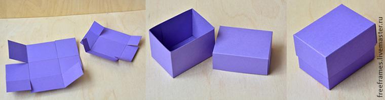
Now, to fix it in the mind, let's vary the sizes. For example, the length of the box is 20 cm, the width, for example, is 10, and the height is 15 cm. We calculate: 15 + 20 +15 = 50 cm (this is the length of the sweep), and 15 + 10 +15 = 40 cm (this is the width of the sweep ).
If you need a box with a square bottom, then the scan will turn out to be square. For example: the size of the bottom of the box should be 20 x 20 cm, and the height should be 15 cm. It is easy to calculate: 15 + 20 + 15 = 50 - which means that a square of 50 x 50 cm is needed to build a sweep
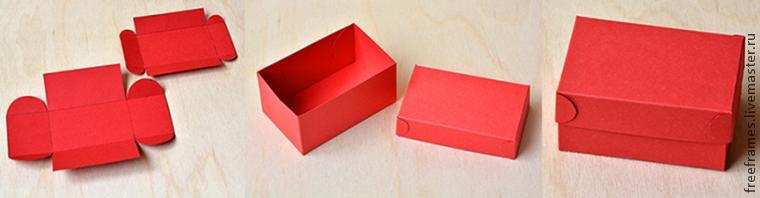
You can make a slightly different version of the sweep: on two opposite sides, two pairs of "ears" for fastening. (You can leave the "ears"-squares, or you can round them)

Have you noticed that the larger the box is needed, the less likely it is to “fit” the scan into a single standard sheet? What to do? Compose from individual parts!
For example, in one direction the reamer “fits in”, but in the other it does not fit. So, we glue two sides. Just do not forget about the "increase" for connecting parts! It is enough to make 1.5-2 cm per increase - everything will stick perfectly.

And if the box is so big that you can’t even fit the sides in one direction, then you can glue all the sides + the bottom. In addition, this method is suitable not only for large boxes: you can also glue a small one, if, for example, it is planned that all sides will be multi-colored.
The calculations in this case are also extremely simple. Bottom (in the photo - green detail): let there be a square of 20 x 20 cm and another increase on each side of 1.5 cm. It turns out 1.5 + 20 + 1.5 = 23 cm just cut it out - so that they do not interfere with bending the additions up for assembly.
Let's assume that the height of the box should be 40 cm! This means that two opposite walls of the box will have a size of 1.5 + 20 + 1.5 cm - this is the width, and the height is 40 cm (blue details in the photo). And the other two opposite sides do not need an increase: we draw two parts 20 x 40 cm (in the photo - red parts)

There are cases when only this method is suitable - gluing in parts. For example, if very thick and dense cardboard is used. In this case, even an increase is not needed: the glue is applied to the thickness of the blanks. There, when making calculations, it is necessary to take into account the thickness of the cardboard very carefully!
It’s not at all difficult to calculate the lid for our box: again we draw a square or rectangle with the same dimensions as at the bottom of the box, but be sure to add double the thickness of the cardboard. Be careful here: a lot depends on how the lid is glued. If you plan to bend the “ears” inward, then the increase will turn out to be larger. In my classes, I recommend that students glue “ears” on the outside. We just give them a neat shape (ovals, for example) and glue on the outside. Looks pretty decorative.
The master class has come to an end! The material presented here may seem primitive to some, however, do not rush to criticize - I quite often encounter situations in practice when it is difficult for people to imagine how to fold a three-dimensional structure from a flat sheet, having previously calculated its dimensions. Therefore, I propose to consider this information auxiliary. If anyone has a problem making a box of a certain size, I hope the tricks shown here will help solve it!
A match is a thin wooden handle, equipped with an incendiary head on top. The main purpose of this wand is to obtain an open fire. Not a single person can do without matches today. With their use, they light gas in the kitchen, make a fire in the forest, smoke, etc. Matches are small in size, and therefore they are usually used in large quantities. It would be extremely inconvenient to store them in bulk. So they put them in small boxes. The latter can contain them in several tens, hundreds or even thousands of pieces. The size of the matchbox, respectively, may be different. However, there are still certain standards for height, width and length.
A bit of history
The matches themselves were invented in 1805 by the physicist J. Chansel. For a long time they were sold without a box. The size of the matches at that time were larger than now, and they were lit on any hard surface. The first box for storing them supposedly appeared in 1833. Initially, the grater was located inside. It was not very convenient, of course, and the fact that matches in such boxes sometimes spontaneously ignited simply due to friction against each other.
Safety matches began to be produced only in the middle of the 19th century. in Sweden. They appeared in Russia in the 1880s. Initially, those supplied from were very expensive in our country, only wealthy people could use them.
Standard matchbox size
Such products are made today most often from ordinary thick cardboard. On sale there are pocket versions of matchboxes, household, fireplace, etc. But most often, of course, the first variety of such cardboard products is used.
The standard size of a matchbox is determined by GOST 1820-2001. What exactly should be the dimensions of this product, see the table below.
As you can see, the length of a standard box is not five centimeters, as everyone used to think. This figure is slightly higher. The size of a matchbox in centimeters is 5.05x3.75x1.45. The matches themselves are produced with a length of 42.5 mm, a thickness of 2.05 mm. There should be 45 matches in a box, but in some cases their number can be reduced to 38. It is interesting that in Soviet times, according to the standards, at least 60 matches should have been packed in boxes of this size.
Label design and ease of use
The matchbox is a regular cardboard parallelepiped, both sides of which are covered with labels. The design of the latter can be anything, but it is not the same. The labels are arranged in such a way that the consumer can immediately understand exactly how the inside of the box is turned. If they had the same design, matches would be very easy to scatter when opened. Most often, on the front labels of modern boxes, logos of different companies are depicted, and on the reverse side - their contact information.

What other standards exist
GOST standards, in addition to different label designs, in the manufacture of matchboxes, the following are observed:
Instead of two, one label (on the top side) is allowed.
The inside of the box should be tightly held in the outside and not fall out with any change in its position.
The flow of the phosphor grater on the wide side of the box should not exceed 4 mm.
The label must not extend more than 1 mm onto the narrow part.
The total area of the grater's phosphorus mass should ensure the free ignition of a double number of matches in the box.
As for the matches themselves, sparks and burning slag are not allowed to fly off when they are ignited. The head must be at least 2.5 mm long. The presence of sulfur streaks is not allowed. Below we present to your attention a drawing of a matchbox with dimensions (standard).

How is it stored and transported
Filled matchboxes are packed according to GOST 13511-91. First, they are wrapped in paper packs of 10 pieces. Then put into cardboard boxes. The latter are transported in covered transport in a packaged state. Such products cannot be transported on open platforms. After all, when wet, matches will become unusable for use. Store matches at a temperature of no more than 40 degrees and a humidity of 85%.
Other sizes
Standard matches are sold in every grocery store and tobacconist. But sometimes in the shopping center you can see boxes of other sizes. For example, on sale sometimes there is a similar in shape and design to the standard version "700" or "500". The size of a matchbox of this variety can be 92x80x46 mm (for 700 pieces) or 52x70x132 (for 500 pieces). Of course, you can’t put such a product in your pocket, but for the kitchen it can be quite convenient.
You can also purchase Household matches in very large boxes - 75x225x155 mm or 47x196x130 mm. This option has a slightly different design than the usual one. There is no retractable part. It is installed vertically and opens from above. Such dimensions of matchboxes allow you to put 2000 pieces in them. matches (both in one and in the other).

Matches can be sold not only in boxes, but also in beautiful jars. This option is also well suited for thrifty housewives. Matches in such jars can be poured 1100-1500 pieces. In addition, this option will look very good in the kitchen.
How to make a beautiful matchbox with your own hands
Such a souvenir is perfect as a gift to guests if the celebration is organized, for example, in nature. Those invited will be able to use it for its intended purpose or take it home with them as a keepsake. It is best if the size of the matchbox used in this case as a frame is standard. But you can use any other option. You should also prepare beautiful paper, ribbons and invisible (hairpins).
The box is removed and the upper part is unfolded. Beautiful inscriptions are applied to the paper. You can make them by hand. But it is better to find a template on the Internet and print it on a printer. Next, the paper is cut to size box (2 large walls and 1 small). It should be glued in such a way that 1 grater remains visible. Rough edges can be trimmed using scissors and a ruler. Next, the box must be carefully glued again. In order for the paper not to leave, you can use invisibility. After the glue dries, you can insert the matchbox itself into a beautiful shell.

To make the souvenir look even more attractive, it should be tied with a beautiful ribbon, making a bow or a rose. Sometimes in such gift boxes, instead of matches, a piece of bright toilet soap of a suitable size is placed. In this case, a very interesting souvenir is also obtained. What size of matchbox to choose in this case is not a very important question. It will look beautiful as a small souvenir with soap, as well as a large one.

Fancy boxes
Of course, if you wish, you can also purchase a finished model of such an original souvenir. For example, calendar boxes, products divided into two parts (for whole matches and burnt ones) or with holes for candles look very nice. An interesting gift can also be, for example, a wooden box designed for only one match, cowboy, etc.
The horizontal and vertical projections of a point, as we have just established, completely set us its position in space. In practice, when depicting spatial forms, it is often necessary to also use a third, or profile, projection plane. It is chosen perpendicular to the first two. Therefore, everything that has been said about a system of two planes will also be true in relation to a system of three planes.
However, before proceeding to the construction and reading of production drawings, let's return to the task that we set at the beginning of this chapter. Let's find out how the individual views were obtained, which are shown in the drawing of a matchbox (see Fig. 10). We already know now that they are its rectangular projections on three mutually perpendicular planes. In contrast to the designations of horizontal and vertical projections of points, the projection of a point, for example A, onto a profile plane is denoted as follows: A "" (pronounced "a three strokes"). It remains to consider now how the transition from the spatial system of three planes to the zpure is carried out.
We agree to continue to assume that the vertical plane of projections coincides with the plane of the drawing. Compatible with the same plane and the other two: horizontal and profile. To do this, we rotate each of them around the line of its intersection with the vertical plane, as about the axis of rotation. The direction in which each plane is rotated until it aligns with the drawing plane is shown in FIG. 19 circular arrows. The combined positions of the horizontal and profile planes are indicated in this figure by the numbers I and III, underlined with two lines. The designations of the combined positions of the horizontal and vertical projections of the box are underlined in the same way.
The result of the performed combination of planes is a diagram. In this case, it corresponds to a system of not two, but three projection planes. Since on the diagram we have a collection of individual views of the same object, such an image has recently been called a complex drawing in rectangular projections.
If now the diagram marked in Fig. 19 digits
I II and III, show simplified, i.e. without frames and without
The designations of the projections of the object themselves, then we will come to the drawing placed in Fig. 10. We only note that FIG. 19 and 10 are made in different scales.
We are familiar with the way in which the transition from the object to its drawing is carried out. And what about the reverse task?
The effects of the arrows into directly opposite ones, we will be able to imagine the object depicted on it from the drawing.
Our short excursion to the area of * * production drawings is over. She introduced us to many interesting and important things. We have seen how the graphic language has improved over time. From…
We have already found out the name and material of the part shown in Fig. 35. We also found out that the mandrel was drawn in full size. Now let's move on to projections and try to imagine its shape from them. …
The name of the part, the designation of the scale in which it is drawn, the conditional code of the material used for its manufacture, and some other information are reported by the main inscription. This inscription is a kind of "passport", which is supplied ...
The next step is to convert our box into an Editable Poly object: RMB -> Convert to -> Editable Poly.

Select two sides of the box, as shown in the figure:

With a tool Inset create new polygons with a slight indent in 0.045 cm:

Delete these faces, and connect the remaining parts through the tool Bridge. If we select all the edges we need and use the command Bridge, then nothing will work, since the program will not understand what to connect with what. And therefore it is better to connect all the edges separately.


For the inner box, we will create box, which we will make a little smaller than the main box:

Delete the topmost edge ( Poligon face) and apply to the whole box modifier Shell, which adds thickness to our object:


Let's add some smoothness to our main box. Why select four edges, as shown in the figure, and apply the tool to them Chamfer:


Now we have all the objects ready. It remains to make UVs for them, so that it is more convenient to paint them in photoshop or Substance Painter.

Step 4: UV Unwrapping Our Objects
Box 1
We will do the scan using the means of 3ds Max itself, using the modifier Unwrap UVW. So let's select our main box and apply a modifier to it Unwrap UVW. Open the sweep editor by clicking on the button Open UV Editor:


First of all, uncheck Select by Element. This is necessary so that when selecting an object, you can select its faces and edges, and not its entirety.

One way to create UV layout is through the use of object edges. That is, we can select the edges we need to divide the model:


This is how you need to select the edges of interest to us and click the icon Quick Planar Map:

But we will do it a little differently. Let's choose the ability to select only faces by selecting the icon of this very face from the three options.

And select the edges as shown in the picture (note I have selected 2 edges on the box).

In the flat pattern editor, drag the selected face to the side outside the border of the area that is indicated by the checkerboard texture. We will do the same with the rest of the sections (see pictures). Just click on the button ctrl a few edges and move them to the side for now.


When you unfold the whole box in this way, you can sew some parts for ease of texturing. If you select one edge in the UVW editor, you will see that the program highlights another edge that is associated with it. Don't forget to select the edge icon to be able to manipulate the edges in the editor.


We sew the ribs we need. Selecting an edge and clicking the icon Stitch: Custom. You can cut any parts through the tool Break. This is how I sewed the pieces of the scan I needed:

If you need to rotate a part in the UV editor, select the rotate tool. To rotate at an angle of 10°, hold down ctrl.

Arrange the details of the model as you see fit. I got something like this:

To decompose everything automatically, you can select a tool Pack: Custom.
In order to scale our parts according to their true size in relation to other parts, we can use the tool Rescale Elements(see picture). However, for some reason it doesn't always work. For example, he could not properly adjust the development of the sulfur head of the match for me. And I had to scale it manually.

Box 2
Let's move on to the development of the second box.

Turning off the selection of the entire object Select by Element. Select only the lowest face, then press the button Grow.

This will select nearby model faces. Send it all to the UV editor by selecting Quick Planar Map.

The result is something uneven. However, you should not worry! We'll just cut the edges and get a nice sweep. Select the edges shown in the picture.


In the way already known to us, select through ctrl two edges.

And send this piece to the editor. If the desired piece of geometry is not located quite correctly, then you can straighten it with the tool Relax – Relax Until Flat or Relax: Custom.

Expanding all other faces in the same way, compose all Pack: Custom and move to the side.

Match
Now let's deal with the UV unwrapping of the match. Everything is similar to the previous steps. First, convert our box to an editable polygon: PKM(right mouse button), Convert To -> Convert to Editable Poly.

All steps repeat all the operations that we did above.

Look closely at the picture and you will succeed. When selecting the entire model, do not forget to indicate that you are working with polygons by clicking on the icon Polygon:
I want to draw your attention to the fact that when choosing the upper faces of a match, which, in fact, are smaller than all the others, this can happen (see picture).

All this is easily edited by selecting a tool. Pack: Custom, which lays out all the details within the desired area, scaling them to the actual size along the way. Also, as mentioned above, you can use the tool Rescale Elements.

It should turn out something like this:

Select everything and move aside.
With a head of sulfur, I was not very smart. At first, I chose what the program created automatically for me. Then I played a little with other instruments, which I already wrote about above. You can also cut it your way.

To get all the elements on the same UV sheet - I selected them and applied a modifier to all Unwrap UVW.

And here's what I got.

Step 5: Create a UVW Pattern for the Texture
Now we need to create a template that will help us create the box texture in Photoshop. To do this, in the editor Edit UVW select from the menu Tools string Render UVW Template(see picture).

In the opened window Render UVs select the desired resolution for the future texture. I chose 1024X1024. The rest of the settings can be left as default. They affect the appearance of the resulting template. You can play around with them if you want something more comfortable for you. Next, click the button Render UV Template.

Click the icon Save, select the desired format, the name of your template and click the button Save.
Step 6: Label for the box
Now it's the turn to launch Photoshop or any other raster or vector graphics editor. And open our template in it. The textures you need can be found at the wonderful site textures.com. I use http://www.bluevertigo.com.ar/ to find textures. This is a small database of sites with textures.

Also, no one forbids you to use the scanner. By digitizing every possible box in your home.
5.1. View Arrangement Rules. To fully reveal the shape of objects in drawing, various images are used: views, sections, cuts. First, you will study the views.
View- this is the image of the visible part of the surface of the object facing the observer. To reduce the number of images, it is allowed to show in the views the necessary invisible parts of the surface of the object using dashed lines. And Difference from projections on views apply some conventions and simplifications. You will study them later.
The image obtained on the frontal projection plane is called front view. This image is taken in the drawing for the main thing. Therefore, this type is also called the main one. When making a drawing, the object must be positioned relative to the frontal plane of projections so that the main view gives the most complete idea of the shape and size of the object.
The image on the horizontal projection plane is called top view.
The image on the profile plane of projections is called left view.
Along with front, top, and left views, right, bottom, and back views can be used to depict an object (all of them are called basic). However, the number of views in the drawing should be the smallest, but sufficient to fully reveal the shape and size of the object. To reduce the number of views on them, it is allowed to show, if necessary, invisible parts of the surface of the object with dashed lines. For the same purpose, various symbols, signs and inscriptions established by the standard are used.
Rice. 52. Three kinds of detail
Figure 52 shows three views of the part illustrated in Figure 53. The main view is the front view. Below it is a top view, to the right of the main view and at the same height - the left view. The cutout in the rectangular part turned out to be invisible in the top view, so it is shown with a dashed line.

Rice. 53. Visual representation of the detail
5.2. local views. In some cases, in the drawing, instead of a full view, you can apply a part of it. This simplifies the construction of the image of the subject.
The image of a separate, limited place on the surface of an object is called local view. It is used in that case. when it is required to show the shape and dimensions of individual elements of the part (flange, keyway, etc.).
The local view can be limited to a cliff line, an axis of symmetry, etc. It can be marked on the drawing and an inscription. A local view is placed on a free field of the drawing or in a projection connection with other images. At school, you will consider local views located only in the projection relationship (Fig. 54).

Rice. 54. Local views located in the projection relationship
The use of a local view allows you to reduce the amount of graphic work, save space on the drawing field.
- Define a species.
- How are views arranged on a drawing?
- What type is called the main one and why?
- What species is called local? For what purpose is it used? What gives the use of a local species?


Rice. 56. Task for exercises
Draw the data in Figure 56 and the drawings into the workbook and complete them with the image of the second box.
Instructions for work. If you find it difficult to solve the problem, make models from boxes, as shown in Figure 56, and compare the drawings of the models you made with their visual images. Make yourself one or two more models of two or three matchboxes and complete their drawings.
Practical work No. 3
Modeling from a drawing


Rice. 58. Tasks for practical work No. 3
Instructions for work. Modeling is the process of making a model of an object according to a drawing. You have already done this in labor lessons. Before you start modeling, you need to prepare the necessary material: cardboard, wire.
To make a model out of cardboard, first cut it out. Determine the dimensions of the workpiece according to the image of the part (see Fig. 58). Mark (outline) cutouts. Cut them along the outlined outline. Remove the cut out parts and bend the model according to the drawing. To prevent the cardboard from straightening after bending, draw a line on the outside of the bend with some sharp object.
The wire for modeling must be used soft, of arbitrary length.