Do-it-yourself power generators. Do-it-yourself free energy generator: diagram
The universal use of electricity in all spheres of human activity is associated with the search for free electricity. Because of this, a new milestone in the development of electrical engineering was an attempt to create a free energy generator that would significantly reduce the cost or reduce the cost of generating electricity to zero. The most promising source for the implementation of this problem is free energy.
What is free energy?
The term free energy arose at the time of the large-scale introduction and operation of internal combustion engines, when the problem of obtaining electric current directly depended on the coal, wood or oil products spent for this. Therefore, free energy is understood as such a force, for the production of which there is no need to burn fuel and, accordingly, to spend any resources.
The first attempts to scientifically substantiate the possibility of obtaining free energy were laid by Helmholtz, Gibbs and Tesla. The first of them developed the theory of creating a system in which the generated electricity must be equal to or greater than that spent for the initial start-up, that is, obtaining a perpetual motion machine. Gibbs expressed the possibility of obtaining energy during the course of a chemical reaction so long that it was enough for a full-fledged electricity supply. Tesla observed energy in all natural phenomena and expressed the theory of the presence of ether - a substance that permeates everything around us.
Today you can observe the implementation of these principles for obtaining free energy in. Some of them have long stood at the service of mankind and help to obtain alternative energy from wind, sun, rivers, tides. These are the same solar panels, hydroelectric power plants that helped to curb the forces of nature, which are freely available. But along with already justified and implemented free energy generators, there are concepts of fuelless engines that try to circumvent the law of conservation of energy.
The problem of conservation of energy
The main stumbling block in getting free electricity is the law of conservation of energy. Due to the presence of electrical resistance in the generator itself, connecting wires and other elements of the electrical network, according to the laws of physics, there is a loss of output power. Energy is consumed and its replenishment requires constant replenishment from the outside, or the generation system must create such an excess of electrical energy that it is enough to power the load and maintain the operation of the generator. From a mathematical point of view, a free energy generator should have an efficiency of more than 1, which does not fit into the framework of standard physical phenomena.
Diagram and design of the Tesla generator
Nikola Tesla became the discoverer of physical phenomena and created many electrical devices based on them, for example, Tesla transformers, which are used by mankind to this day. Throughout the history of his activity, he has patented thousands of inventions, among which there is more than one free energy generator.
Rice. 1: Tesla Free Energy Generator
Look at Figure 1, here is the principle of generating electricity using a free energy generator assembled from Tesla coils. This device involves obtaining energy from the ether, for which the coils included in its composition are tuned to a resonant frequency. To obtain energy from the surrounding space in this system, the following geometric relationships must be observed:
- winding diameter;
- wire sections for each of the windings;
- distance between coils.
Today, various applications of Tesla coils are known in the design of other free energy generators. However, no significant results of their application have yet been achieved. Although some inventors claim the opposite, and keep the result of their developments in the strictest confidence, demonstrating only the final effect of the generator. In addition to this model, other inventions of Nikola Tesla are known, which are generators of free energy.
Magnetic free energy generator
The effect of the interaction of a magnetic field and a coil is widely used in. And in a free energy generator, this principle is used not to rotate a magnetized shaft by supplying electrical impulses to the windings, but to supply a magnetic field to an electric coil.
The impetus for the development of this direction was the effect obtained by applying voltage to an electromagnet (a coil wound on a magnetic circuit). In this case, a nearby permanent magnet is attracted to the ends of the magnetic circuit and remains attracted even after the coil is powered off. A permanent magnet creates a constant flux of a magnetic field in the core, which will hold the structure until it is torn off by physical force. This effect was applied in the creation of a permanent magnet free energy generator circuit.
 Rice. 2. The principle of operation of the generator on magnets
 Look at Figure 2, to create such a free energy generator and power the load from it, it is necessary to form an electromagnetic interaction system, which consists of:
- starting coil (I);
- locking coil (IV);
- supply coil (II);
- support coil (III).
The circuit also includes a control transistor VT, a capacitor C, diodes VD, a limiting resistor R and a load Z H.
This free energy generator is turned on by pressing the "Start" button, after which the control pulse is applied through VD6 and R6 to the base of the transistor VT1. When a control pulse arrives, the transistor opens and closes the circuit for the flow of current through the starting coils I. After that, electric current flows through the coils I and excites the magnetic circuit, which will attract a permanent magnet. The magnetic field lines will flow along the closed circuit of the magnet core and the permanent magnet.
EMF is induced from the flowing magnetic flux in coils II, III, IV. The electrical potential from the IV coil is fed to the base of the transistor VT1, creating a control signal. The EMF in coil III is designed to maintain the magnetic flux in the magnetic circuits. The EMF in coil II provides power to the load.
The stumbling block in the practical implementation of such a free energy generator is the creation of a variable magnetic flux. To do this, it is recommended to install two circuits with permanent magnets in the circuit, in which the lines of force have the opposite direction.
In addition to the above free energy generator on magnets, today there are a number of similar devices designed by Searle, Adams and other developers, the generation of which is based on the use of a constant magnetic field.
Followers of Nikola Tesla and their generators
The seeds of incredible inventions sown by Tesla created in the minds of applicants an unquenchable thirst to translate into reality the fantastic ideas of creating a perpetual motion machine and send mechanical generators to the dusty shelf of history. The most famous inventors used the principles set forth by Nikola Tesla in their devices. Consider the most popular of them.
Lester Hendershot
Hendershot developed a theory about the possibility of using the Earth's magnetic field to generate electricity. Leicester presented the first models back in the 1930s, but they were never in demand by his contemporaries. Structurally, the Hendershot generator consists of two counter-wound coils, two transformers, capacitors and a movable solenoid.
 Rice. 3: general view of the Hendershot generator
 The operation of such a free energy generator is possible only with its strict orientation from north to south, therefore, a compass must be used to set up the work. Coils are wound on wooden bases with multidirectional winding to reduce the effect of mutual induction (when EMF is induced in them, EMF will not be induced in the opposite direction). In addition, the coils must be tuned by a resonant circuit.
John Bedini
Bedini introduced his free energy generator in 1984, a feature of the patented device was an energizer - a device with a constant torque that does not lose momentum. This effect was achieved by installing several permanent magnets on the disk, which, when interacting with the electromagnetic coil, create impulses in it and repel from the ferromagnetic base. Due to this, the free energy generator received the effect of self-feeding.
Later Bedini generators became known through a school experiment. The model turned out to be much simpler and did not represent something grandiose, but it was able to perform the functions of a generator of free electricity for about 9 days without outside help.
 Rice. 4: circuit diagram of the Bedini generator
 Look at Figure 4, here is a schematic diagram of the free energy generator of that same school project. It uses the following elements:
- a rotating disk with several permanent magnets (energizer);
- a coil with a ferromagnetic base and two windings;
- battery (in this example, it was replaced with a 9V battery);
- control unit of a transistor (T), resistor (R) and diode (D);
- the current collection is organized from an additional coil that feeds the LED, but it can also be powered from the battery circuit.
With the start of rotation, permanent magnets create a magnetic excitation in the core of the coil, which induces an EMF in the windings of the output coils. Due to the direction of the turns in the start winding, the current begins to flow, as shown in the figure below, through the start winding, resistor and diode.
 Rice. 5: Starting the Bedini Generator
 When the magnet is directly above the solenoid, the core is saturated and the stored energy becomes sufficient to open the transistor T. When the transistor is opened, the current begins to flow in the working winding, which recharges the battery.
 Figure 6: Starting the floating charge winding
 The energy at this stage becomes sufficient to magnetize the ferromagnetic core from the working winding, and it receives the pole of the same name with a magnet located above it. Thanks to the magnetic pole in the core, the magnet on the spinning wheel is repelled from this pole and accelerates the further movement of the energizer. With the acceleration of the movement, the pulses in the windings occur more and more often, and the LED switches from a flashing mode to a constant glow mode.
Alas, such a free energy generator is not a perpetual motion machine; in practice, it allowed the system to work ten times longer than it could operate on a single battery, but eventually it stops anyway.
Tariel Kapanadze
Kapanadze developed a model of his free energy generator in the 80s and 90s of the last century. The mechanical device was based on the work of an improved Tesla coil, as the author himself claimed, a compact generator could feed consumers with a power of 5 kW. In the 2000s, an industrial-scale 100 kW Kapanadze generator was built in Turkey; according to its technical characteristics, it needed only 2 kW to start and operate.
 Rice. 7: Kapanadze generator circuit diagram
 The figure above shows a schematic diagram of a free energy generator, but the main parameters of the circuit remain a trade secret.
Practical schemes of free energy generators
Despite the large number of existing free energy generator circuits, very few of them can boast of real results that could be tested and repeated at home.
 Rice. 8: Tesla generator working diagram
 Figure 8 above is a free energy generator circuit that you can replicate at home. This principle was set forth by Nikola Tesla, for its operation a metal plate is used, isolated from the ground and located on some kind of hill. The plate is a receiver of electromagnetic oscillations in the atmosphere, this includes a fairly wide range of radiation (solar, radio magnetic waves, static electricity from the movement of air masses, etc.)
The receiver is connected to one of the capacitor plates, and the second plate is grounded, which creates the required potential difference. The only stumbling block to its industrial implementation is the need to isolate a large plate on a hill to power at least a private house.
Modern look and new developments
Despite the widespread interest in creating a free energy generator, they still cannot oust the classical method of generating electricity from the market. The developers of the past, who put forward bold theories about a significant reduction in the cost of electricity, lacked the technical perfection of the equipment or the parameters of the elements could not provide the desired effect. And thanks to scientific and technological progress, humanity receives more and more new inventions that make the embodiment of a free energy generator already tangible. It should be noted that today free energy generators operating on the power of the sun and wind have already been received and actively operated.
But, at the same time, on the Internet you can find offers to purchase such devices, although for the most part these are dummies created to deceive an ignorant person. And a small percentage of really working free energy generators, whether they are based on resonant transformers, coils or permanent magnets, can only cope with the power supply of low-power consumers, they cannot provide electricity, for example, to a private house or lighting in the yard. Free energy generators are a promising direction, but their practical implementation has not yet been implemented.
The electric generator is the main element of an autonomous power plant. If there is no electricity in your private house or cottage, you are wondering how you can fix this problem yourself?
Perhaps an excellent solution would be to purchase an electric generator in a distribution network. But the cost of even low-power models starts at 15,000 rubles, so you need to look for another way out. It turns out he is. It is quite possible to assemble an electric generator with your own hands, and connect it.
This will take a little. Skills in handling tools and knowledge of the basics of electrical engineering. The main engine of the process will be your desire, which is a time-consuming and responsible procedure. An additional incentive will be the possibility of saving a large amount of money.
Do-it-yourself power generators for the home: ways to implement
A bit of theory. The basis for the occurrence of an electric current in a conductor is the electromotive force. Its appearance occurs as a result of exposure to the conductor, a changing magnetic field. The magnitude of the electromotive force depends on the rate of change of the flux of magnetic waves. This effect underlies the creation of synchronous and asynchronous electrical machines. Therefore, it is not difficult to convert a current generator into an electric motor and vice versa.

For a country house or summer cottage, a DC generator is used extremely rarely. It can be used in a special version for the welding machine. Basically, its scope extends to industry. The alternator is designed to generate electricity in large quantities, so in the country or in a country cottage, it will be an excellent alternative to central power supply. Therefore, to create an alternator at home, we will do the conversion of an asynchronous electric motor with our own hands. The principle of operation of an alternator is to convert mechanical energy into electrical energy. An example of an elementary electrical generator can be seen in the video.
This unique way of producing light is very interesting. Having slightly improved it, we get the opportunity to provide ourselves with lighting on a hike or in nature. The only condition is that you will have to ride a bicycle, taking a small but necessary device.
In this case, to obtain a rotating electromagnetic field of the conductor, we start the engine. Often an internal combustion engine is used. Fuel burning in the combustion chamber gives a reciprocating motion to the piston, which through the connecting rod causes the crankshaft to rotate. He, in turn, transmits rotational motion to the generator rotor, which, moving in the magnetic field of the stator, generates an electric current at the output.
The alternator consists of the following parts:
- a body part made of steel or cast iron, which acts as a frame for mounting the stator and rotor bearing assemblies, a casing to protect the entire internal filling from mechanical damage;
- ferromagnetic stator with magnetic flux excitation winding;
- movable part (rotor) with a self-excited winding, the shaft of which is driven by an external force;
- a switching unit that serves to remove electricity from a moving rotor using graphite current-collecting contacts.
The fundamental components of an alternator, regardless of the amount of fuel consumed and engine power, are the rotor and stator. The first creates a magnetic field, and the second generates it.
Unlike synchronous generators, which have a complex design and lower productivity, an asynchronous analogue has a whole list of significant advantages:
- Higher efficiency, losses are 2 times lower than those of synchronous generators.
- The simplicity of the case does not reduce its functionality. It reliably protects the stator and rotor from moisture and used oil, which increases the overhaul period.
- Resistant to voltage drops, in addition, the rectifier installed at the output protects electrical appliances from damage.
- It is possible to supply power to high-sensitivity devices with an ohmic load.
- Durable. The service life is calculated in tens of years.
The main components of an electric generator are a system of coils and a system of electromagnets (or other magnetic system).
The principle of operation of an electric generator is to convert rotational mechanical energy into electrical energy.

The system of magnets creates a magnetic field, and the system of coils rotates in it, turning it into an electric field.


In addition, the generator system includes a voltage tapping system that connects the generator itself to current consuming devices.
One of the easiest ways is to use an asynchronous generator.

To create an electric generator, we need two main elements: an asynchronous generator and a 2-cylinder gasoline engine.

The gasoline engine must be air-cooled, 8 horsepower and 3000 rpm.

An ordinary electric motor with a power of up to 15 kW and a speed of 750 to 1500 rpm will act as an asynchronous generator.
The frequency of rotation of the asynchronous for normal operation must be 10 percent higher than the synchronous number of revolutions of the electric motor used.
Therefore, an asynchronous motor must be untwisted to a speed of 5-10 percent higher than the nominal. How can this be done?
We proceed as follows: we turn on the electric motor in the network, after which we measure the idle speed with a tachometer.
What is meant? Consider the example of an engine whose rated speed is 900 rpm.

Such an engine, when idling, will produce 1230 rpm.
Thus, in the case of the given data, the belt drive must be designed to provide the generator speed, and equal to 1353 rpm.
The windings of our asynchronous are connected by a "star". They generate a three-phase voltage, with a power of 380 V.
In order to maintain the rated voltage in the asynchronous circuit, it is necessary to correctly select the capacitance of the capacitors between the phases.

The containers, there are only three of them, are the same.

If heating is felt, this means that the connected capacitance is too large.
To select the required capacity for each phase, you can use the following data, based on the power of the generator:
- 2 kW - capacitance 60 uF
- 3.5 kW - capacitance 100 uF
- 5 kW - 138 uF
- 7 kW - 182 uF
- 10 kW - 245 uF
- 15 kW - 342 uF
For operation, capacitors with an operating voltage of at least 400 V can be used. When you turn off the generator, an electric charge remains on its capacitors.
Obviously, this means a certain degree of danger of the work being carried out. Be sure to take precautions to avoid electric shock.
The generator allows you to work with hand power tools.
To do this, you will need a transformer from 380 V to 220 V. When connecting a 3-phase motor to a power plant, it may turn out that the generator cannot start it the first time.

This is not scary - it is enough to make a series of short-term engine starts.
They need to be produced until the engine picks up speed.
Another option is to unroll it manually.

The second option to make a 220 \ 380 V electric generator on your own is to use a walk-behind tractor as a base.
The walk-behind tractor is very widely used for plowing and cleaning suburban areas - but this is far from the limit of its useful uses.
As it turned out, and was confirmed by the experience of a huge number of people, it helps to solve the problem with electricity in houses and outbuildings where it is not connected.
We need a walk-behind tractor and an asynchronous electric motor, the speed of which will be from 800 to 1600 rpm, and power - up to 15 kW.
The motoblock engine and the asynchronous motor must be connected. This is done by using 2 pulleys and a drive belt.

Pulley diameter is important. Namely, it must be such as to ensure that the generator speed is exceeded by 10-15% of the nominal speed value in the electric motor.
In parallel to each pair of windings, we turn on the capacitors. Thus, they will form a triangle.
Voltage must be removed between the end of the winding and its midpoint. As a result, we get a voltage of 380 V between the windings, and a voltage of 220 V between the middle and end of the winding.
After that, you need to select capacitors that will ensure the correct start-up and operation of the generator.
Remember that all three generators have the same capacity.
The relationship between generator power and required capacity is as follows:
- 2 kW - capacitance 60 uF
- 3.5 kW - capacitance 100 uF
- 5 kW - 140 uF
- 7 kW - 180 uF
- 10 kW - 250 uF
- 15 kW - 350 uF
It may be sufficient for you to use just one capacitor for the required loads. Other conditions must be selected in practice independently.

A do-it-yourself electric generator can be used, among other things, for heating a private house or cottage.
In this case, you will need a more powerful gasoline engine, for example, from a car, which can be bought at a junkyard.
Connecting an electric generator to a private house how to produce?

- turn off the electricity in the house;
- start and warm up the generator;
- connect the generator to the network;
- watch for the appearance of a normal power supply;
- disconnect the generator from the backup network and turn it off (before that, turn off all working electrical appliances in the house).
Be careful: if you perform these steps in the wrong order, the generator may turn on on the contrary, which will cause a breakdown.
Choosing a generator for the home
To determine what generator power you should choose, you need to evaluate the entire active type of loads.
It takes into account all the light bulbs, electric kettle, microwave, heaters, power tools. That is, all the devices that you plan to use.
For example, if you are going to use a couple of appliances and a few more light bulbs, you should add up the total power they consume.
So, for a situation where you need to make 6 light bulbs with a power of 100 W shine, an oil heater with a power of 1.5 kilowatts and a microwave oven with the same power work, the calculation is as follows: 1.5x2 + 600 (100 W for 6 lamps) \u003d 3.6 kilowatts.
It is this power (or a little more) of the generator that you need.
And also you can watch the video of the electric generator with your own hands
Tailored for you:
A simple generator consists of just a few parts. It doesn't even have radio components!
Let's start with the schematic diagram of this device, here it is:
The design consists of three parts:
- Generator
- Switch
- multiplier
I started the build with a generator.
First, I found a broken coffee grinder (To be honest, I don’t know how to call it correctly, most likely a manual vegetable cutter), here it is:

Later it turned out that it was a vegetable cutter. Here, on the Internet, I found how it looked in working condition:
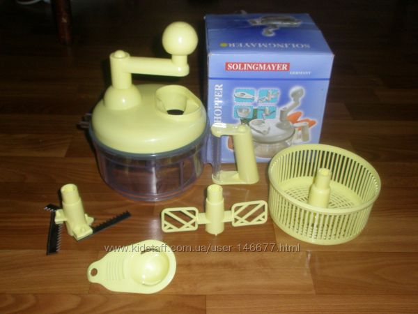
From it I needed only the upper part with a handle. It contains a gearbox - what we need!

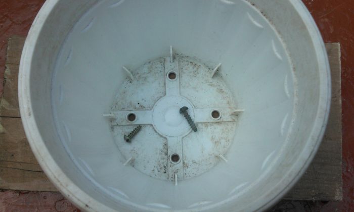
After that, I got a flower pot and an engine from a printer:

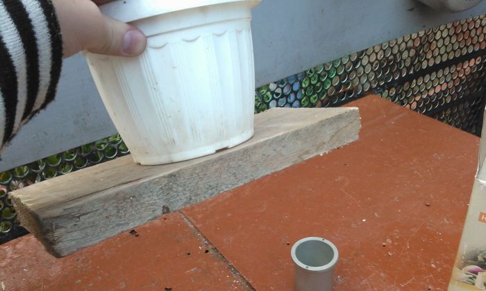
Then I screwed the pot to the board with self-tapping screws (I screwed it to the board to hold it tighter).


I looked at the motor, tried to screw it to the gearbox rotor, but, unfortunately, I failed :(


And then I found the DPM engine:

He approached. I decided to put it on. To do this, I drilled a hole and screwed the motor axle into it (It was threaded):


Previously, I looked to see if the motor was suitable in height, in relation to the bottom of the pot and the height of its walls:

Next, I made two holes on the sides of the pot:


Then I inserted a thick hard wire into them, making a loop under the diameter of the motor housing:


I also made a hole, also in the wall, but closer to the base:

I threaded the wires from the motor into this hole.
After that, almost the very end, it remains only to strengthen our structure - this is at your discretion. Personally, I wrapped the entire device with tape.


Hooray! The device is ready! Now I conducted a test on it - I connected the counters:

The ammeter showed the highest mark.
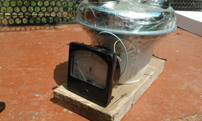
That's basically all ... Our manual generator produces about 2 volts at the output, it also depends on the model of your engine, I had DPM - 30N 2 - 04.
Later I installed a voltage multiplier, here is the most standard doubler circuit (not mine, dug up on the Internet):

List of radio elements
| Designation | Type | Denomination | Quantity | Note | Score | My notepad |
|---|---|---|---|---|---|---|
| Diode | high voltage | 2 | You can take any | To notepad | ||
| Capacitor | 400uF*450V | 2 | For multiplier | To notepad | ||
| Engine | Any | 1 | Any | To notepad | ||
| Ammeter | Any | 1 | You can take another, for example, a voltmeter |
Coziness and comfort in modern housing largely depends on the stable supply of electrical energy. Uninterrupted power supply is achieved in various ways, among which a home-made asynchronous type generator, made at home, is considered quite effective. A well-made device allows you to solve many household problems, from generating alternating current to providing power to inverter welding machines.
The principle of operation of the electric generator
Asynchronous type generators are alternating current devices capable of generating electrical energy. The principle of operation of these devices is similar to the operation of asynchronous motors, so they have a different name - induction generators. Compared to in these units, the rotor turns much faster, respectively, the rotation speed becomes higher. An ordinary AC induction motor can be used as a generator, which does not require any circuit conversions or additional settings.
The inclusion of a single-phase asynchronous generator is carried out under the action of the incoming voltage, which requires the device to be connected to a power source. Some models use capacitors connected in series to ensure their independent operation due to self-excitation.
In most cases, generators require some kind of external driving device to generate mechanical energy, which is then converted into electrical current. Most often, gasoline or diesel engines are used, as well as wind and hydro installations. Regardless of the source of the driving force, all electric generators consist of two main elements - the stator and the rotor. The stator is in a fixed position, providing the movement of the rotor. Its metal blocks allow you to adjust the level of the electromagnetic field. This field is created by the rotor due to the action of magnets located at an equidistant distance from the core.

However, as already noted, the cost of even the most low-power devices remains high and out of reach for many consumers. Therefore, the only way out is to assemble the current generator with your own hands, and put in it all the necessary parameters in advance. But, this is not at all an easy task, especially for those who are poorly versed in circuits and do not have skills in working with tools. The home master must have specific experience in the manufacture of such devices. In addition, it is necessary to select all the necessary elements, parts and spare parts with the necessary parameters and technical characteristics. Homemade devices are successfully used in everyday life, despite the fact that in many respects they are significantly inferior to factory products.
Advantages of asynchronous generators
In accordance with the rotation of the rotor, all generators are divided into synchronous and asynchronous type devices. Synchronous models have a more complex design, increased sensitivity to mains voltage drops, which reduces their efficiency. Asynchronous aggregates do not have such disadvantages. They are distinguished by a simplified principle of operation and excellent technical characteristics.

The synchronous generator has a rotor with magnetic coils, which significantly complicate the process of movement. In an asynchronous device, this part resembles an ordinary flywheel. Design features affect the efficiency. In synchronous generators, efficiency losses are up to 11%, and in asynchronous generators - only 5%. Therefore, the most effective would be a home-made generator from an asynchronous motor, which has other advantages:
- The simple housing design protects the motor from moisture ingress. Thus, the need for too frequent maintenance is reduced.
- Higher resistance to voltage drops, the presence of a rectifier at the output that protects connected devices and equipment from breakdowns.
- Asynchronous generators provide efficient power for welding machines, incandescent lamps, computer equipment that is sensitive to voltage drops.
Thanks to these advantages and a long service life, asynchronous generators, even assembled at home, provide uninterrupted and efficient power to household appliances, equipment, lighting and other critical areas.
Preparing materials and assembling the generator with your own hands
Before starting the assembly of the generator, you need to prepare all the necessary materials and parts. First of all, you need an electric motor, which can be made on your own. However, this is a very time-consuming process, therefore, in order to save time, it is recommended to remove the required unit from the old non-working equipment. Best suited and water pumps. The stator must be assembled, with a finished winding. A rectifier or transformer may be needed to equalize the output current. Also, you need to prepare an electrical wire, as well as electrical tape.

Before you make a generator out of an electric motor, you need to calculate the power of the future device. To this end, the engine is connected to the network to determine the speed of rotation using a tachometer. 10% is added to the result. This increase is a compensatory value that prevents excessive heating of the engine during operation. Capacitors are selected in accordance with the planned power of the generator using a special table.
In connection with the generation of electric current by the unit, it is imperative to ground it. Due to the lack of grounding and poor-quality insulation, the generator will not only quickly fail, but also become dangerous to people's lives. The assembly itself is not particularly difficult. Capacitors are connected in turn to the finished engine, in accordance with the diagram. The result is a do-it-yourself 220V alternator of low power, sufficient to supply electricity to a grinder, electric drill, circular saw and other similar equipment.

During the operation of the finished device, the following features must be taken into account:
- It is required to constantly monitor the temperature of the engine in order to avoid overheating.
- During operation, a decrease in the efficiency of the generator is observed, depending on the duration of its operation. Therefore, periodically the unit needs breaks so that its temperature drops to 40-45 degrees.
- In the absence of automatic control, this procedure must be periodically performed independently using an ammeter, voltmeter and other measuring instruments.
Of great importance is the correct choice of equipment, the calculation of its main indicators and technical characteristics. It is desirable to have drawings and diagrams that greatly facilitate the assembly of the generating device.
Pros and cons of a homemade generator
Self-assembly of the power generator can save significant money. In addition, a self-assembled generator will have the planned parameters and meet all technical requirements.

However, such devices have a number of serious disadvantages:
- Possible frequent breakdowns of the unit due to the inability to hermetically connect all the main parts.
- Generator failure, significant reduction in its productivity as a result of incorrect connection and inaccurate power calculations.
- Working with homemade devices requires certain skills and caution.
However, a homemade 220V generator is quite suitable as an alternative option for uninterrupted power supply. Even low-power devices are able to ensure the operation of basic appliances and equipment, maintaining the proper level of comfort in a private house or apartment.
A pocket flashlight has become an item of equipment for every tourist. Yes, that's the trouble - the energy of the batteries has to be saved. But you can take a power plant with you. It weighs almost as much as a spare 4.5V battery, and it won't take up much more room in your backpack. Let's give a hint: our electric generator homemade camping power station - almost any microelectric motor DC with excitation from permanent magnets, and the energy source is wind.
camping power plant
The principle of operation of a homemade camping power plant - a mini-generator shown in Figure 1. A current generator with a propeller is mounted on a pole. Wires run from the alternator to the bulb. The propeller automatically "follows" the wind with the help of a weather vane - the "tail". The challenge is how to make the power plant as simple and easy as possible. It is also necessary that it be easily disassembled into parts, and the main components could be repaired or remade from improvised means right on the campaign.
Let's start with the generator. The easiest way to get microelectric motors of the Moscow plant "Young Technician" type DP-1 or MDP-1. When purchasing them in the store, try to choose those whose rotor rotates easier. The smallest power plant will turn out if you use microelectric motors of the KM USH-a-38 type, which are produced in Germany and are sold here as spare parts for railway models. And if you have the opportunity to use microelectric motors of the PD-3 type (any series), the power plant will turn out to be the most powerful. True, these engines are the heaviest of all named. The main dimensions of all listed engines are shown in Figure 2.

A propeller is needed to rotate the generator. There are many design options. However, for field conditions, a propeller that can be easily removed from the generator shaft, or with folding blades, is preferable. The removable propeller is shown in Figure 3.
 It is made from the bottom of a can. A boss, machined on a lathe, is soldered into the center. A hole is drilled in the boss and a thread is cut for the M3 screw. The angle of inclination of the blades is about 30°. The number of blades is from 8 to 12.
The simplest design with folding blades is shown in Figure 4. The blades are made of wire, for example, spring wire, brand OBC, 1-1.5 mm in diameter and wrapped in foil. The pointed ends of the wire are stuck into holes pre-pierced in the rubber stopper. The angle of inclination of the blade is the same as in the first design. The central hole in the boss is best drilled with a drill or on a lathe. A tube of suitable diameter 20-25 mm long should be soldered onto the motor shaft. Drill a hole in the boss with a drill with a diameter of 0.5-1 mm smaller than the outer diameter of the tube. Such blades need to be made with a margin, about five, which will allow you to change the characteristic of the propeller depending on the strength of the wind. If you forget your blades at home, don't despair. They can be cut from a suitable piece of wood (fig. 4a) or even feathers of large birds can be used instead.

The wind is usually capricious and often changes direction. Therefore, complete the set of parts with one more - a weather vane. Its designs are shown in figures 1 and 5.

In a plank (Fig. 5) 200-300 mm long, make a groove according to the dimensions of the electric motor. The engine is attached to it with wire, twine or rubber bands from pharmaceutical bottles. Drill a hole as close as possible to the engine in the center of the plank. Here, on a wire pin with a pointed end, the weather vane will be mounted on a pole. To improve its rotation, insert a tube 30-50 mm long into the hole. Drive a nail into the end of the plank. Attach a “tail” to it: a handkerchief, a long ribbon or a bast, like a kite.
The power plant is ready. If necessary, the power plant can be made to work on the go. True, in this case it is better to use a 1.5 V bulb. It will burn brightly enough even in calm weather if you walk at a fast pace.
There is a pocket power plant business and at home. By replacing the light bulb with a DC ammeter of 1-1.5 A or a voltmeter of 3-5 V, you will get a device for measuring wind speed. True, for this you will have to calibrate the scale of indications.
All materials of the section "Ideas for the master"
Home → Electricity → Homemade small wind turbines →
second part windmill installation, readings and electronics
Mini wind generator from a permanent magnet motor
One of the published publications about homemade wind turbines prompted me to build this wind generator.
From this article, I realized that there is nothing particularly difficult in building a small windmill, the main thing is desire. The idea to provide myself with an autonomous source of energy has been in my head for a long time, and after looking at the experiences of others, I decided to build my own windmill.
Such wind turbines were often made on the basis of small DC motors, from all sorts of scanners, drives, and I decided to repeat these rather successful experiments.
At a price, such a wind generator will cost no more than 2-5 thousand rubles, the main price is an electric motor that will be used as a generator. With economical consumption, you can generate 50-250 W, which is much cheaper than solar panels of similar power.
Here, for those who are interested, is my story about how I built the generator.
To build such windmills, you do not need special tools, but enough that almost everyone has in a garage or pantry. To make my design, I only needed a drill, and a jigsaw with which I cut out the blades, and other trifles (keys, bolts, ruler, tape measure, pencil, etc.) in general, what is usually available or purchased in a store for little money.
I myself have a very modest budget, so I decided to make the cheapest possible wind generator, so I was looking for the simplest and most affordable ways to build my windmill.
For the construction, I used the materials available to the maximum and were idle on my site.
P y P f There is nothing complicated in the manufacture of blades.
How to make a mini wind generator with your own hands?
Usually the pipe is divided into three equal parts along, and sawn. Such material is sawn well enough and it can be sawn even with a hacksaw for wood, but I had an electric jigsaw, which made the task easier, although it is also often sawed with metal blades.
To fix it on the shaft, I used an adapter, this is a special nozzle for attaching discs to the shaft.
In the disk, having previously marked out, I drilled holes for the bolts for attaching the blades and assembled everything into a single structure, below you see what I did. I think that it turned out successfully, reliably, simply and accurately.
Next, it was necessary to fix the generator on something, and for this I used a square segment. I didn’t bother with the mount, but simply pulled the generator to the beam with clamps, additionally wrapping it with a casing from a piece of PVC pipe.
 >
>
 >
>
 >
>
 >
>
The tail was cut out of an aluminum sheet, and for mounting in the beam, it was cut along two lines into which the tail is inserted and fixed to the bolts through the drilled holes. I used a piece of pipe and a flange as a rotary axis, which I screwed to the beam after drilling the holes.
Below is a photo of an almost finished wind generator, it remains to build a mast and lift it into the wind.
 >
>
 >
>
 >
>
In the course of assembly, all parts were immediately painted with automotive paint in spray cans.
The mast was assembled from water pipes using ready-made adapters, which greatly facilitated the assembly process without resorting to welding or drilling for bolts. During the assembly process, he worked as a mechanic, working with adjustable wrenches, as if assembling a water assembly.
The result is a fairly strong and reliable mast.
Wind generators from car generators
 >
>
Windmill from an auto-generator with a double stator
Wind generator from "Moto26", made from a car generator with a double stator. The windmill is made to run on a 24 volt battery, with a total power of 300 watts with a wind of 9 m / s. Details and photos in the article.
 >
>
DIY wind generator
Almost completely self-made wind generator, the generator of which was originally supposed to be from a car generator, but after the case was broken, only the stator remained from the generator, and the case had to be made new.  >
>
Wind generator from an auto-generator from Bull
The generator of this windmill is made from a car generator from the truck Bychek.
The stator is rewound with 0.6 mm wire. The rotor is completely new;  >
>
A simple modification of a car alternator
The simplest conversion of a car alternator to permanent magnets.
The generator for this windmill was made from an autogenerator, the stator of which was not changed, but the rotor was equipped with neodymium magnets.  >
>
Wind turbine generator from auto-generator
How to easily and effortlessly remake an oscillator for a homemade wind generator. For alteration, it is not necessary to rewind the stator, do not sharpen the rotor for magnets.
The whole alteration comes down to switching the phases of the generator, and equipping the rotor with small magnets for self-excitation of the rotor.  >
>
Single blade wind turbine propeller
In continuation of the improvement of the wind generator, this time it was decided to try to make a single-blade propeller and see what advantages it gives and what disadvantages are inherent in single-blade propellers.
The blade with a counterweight is not rigidly mounted and can deviate from the axis of rotation up to 15 degrees.  >
>
Wind generator from tractor generator G700
In this wind generator, a tractor generator with electric excitation is used as a generator.
Let's make an electric generator with our own hands
The generator underwent significant changes, the stator was rewound with a thinner wire, and the rotor coil was also rewound. For this windmill, the screw was made of duralumin. Two-bladed propeller with a span of 1.3 m.  >
>
Homemade wind generator for a yacht
A self-made wind generator, the generator of which is made from the generator of the IZH Jupiter motorcycle, This wind generator was specially created for operation on a small yacht, where it was supposed to provide power for navigational instruments and small electronics.
 >
>
New-second wind turbine for a yacht
The new wind turbine used a stator from car generator. The power of the new windmill is now greater, the diameter of the propeller has also increased.
Now the wind generator has a new protection against strong winds, now the screw does not go to the side, but capsizes, and the tail does not fold now, in general, the details are in the article.
 >
>
Windmills flowers from bicycle speakers
Interesting and beautiful windmills, the generators of which are bicycle hub dynamos. They are made in the form of all sorts of flowers, sunflowers, daisies, and painted in the appropriate colors, they look beautiful as a design element.
E-VETEROK.RU wind and solar energy – 2013 Mail: [email protected] Google Plus
Blade calculation and production
This section contains information about the calculation and production of a wind turbine or wind turbine propeller. Calculation of blades for PVC wind turbines, manufacturing of profiled blades. Combined calculation of propeller power and speed, principles of the wind wheel, and conversion of wind energy into mechanical and then into electrical. Comparison and calculation of various types of wind turbines.
 >
>
O, screws, multilayer, vertical
Often beginners from wind turbines cannot decide which propeller they need, how much power a particular wind can give. What diameter do I need to screw and how many blades  >
>
An example of calculating blades from PVC pipes in an Excel spreadsheet
Program for calculation of propellers of wind generators from PVC pipes.
Lots of questions about how to use the table and how to calculate blades. To do this, I gave examples in the article calculating the blades and how to use the table.  >
>
Blade calculator
Program for calculation of PVC plates. The program itself is an Excel spreadsheet that displays all the necessary information for a screw.
You need to enter data in the yellow boxes to get the blade coordinates as well as traffic, power, etc. data.  >
>
Multi-screw propeller or small blade
I decided to describe the main differences between multi-turn wind turbines with small blades.
Many people believe that slow-acting multi-stage propellers have an advantage in low winds and high-speed non-foggy strong winds, but this is not the case.  >
>
Blade angle calculation, twisting
Once again in the independent calculation of the blades, this time we calculate the exact angle of the blades from the wind and the required speed.
DIY mini generator
Calculate the blade drilling for a particular generator. In this article, there are several factors that affect the calculations.  >
>
Create a windmill and calculate it in simple words
How to create a wind generator, where to start and what to start when thinking about a future wind generator.
In this article, I described the main provisions of the principles of wind turbines, vertical and horizontal, without formulas.  >
>
How to make blades for a wind turbine
Very often, the blades are made from sewer pipes, and at the same time they do everything with their own eyes, so such slices have a small Kyiv. The article presents examples of calculating blades from a tube with a special program in the form of a high-pressure plate and cutting dimensions for the blade.
 >
>
Wind wheel calculation, wind generator power
How to calculate the power of a wind generator? - in fact, it's all easier, as it seems, to be the main thing to understand. Formula for calculating the wind force acting on the propeller, plus the KIEV propeller, generator efficiency, wire losses, controller, battery.
 >
>
Calculation of PVC pipes
The product has many ready-made, calculated screws for choosing a wind turbine. Also spreadsheets. The calculated screws have all the necessary data, including the coordinates of the sample of the cutting blade from the pipe.  >
>
Folding tail calculation
Protect the wind generator from strong winds by moving the windshield in the direction of the rotation axis and folding the tail.
Spreadsheets calculate excel as well as formulas and description of the working principle of this wind turbine hurricane protection.  >
>
Working principle horizontal and vertical
Principles of operation of vertical wind generators of the Savonia type and horizontal wind winds. Description of the influence of the wind, as well as the characteristics and characteristics of the processes that allow the rotation of the wind.  >
>
Calculation of vertical wind turbines
An example of the calculation of vertical wind turbines of the Barrel type for beginners to understand where it starts.
The article provides an example of a general calculation of the power and speed of a wind wheel with 2 * 3 m  >
>
How to make a wind tunnel from a car generator
The article describes in detail the process of manufacturing a fan from a car generator.
Since the generator has been processed to produce a propeller and controller. As a rule, she answers all the basic questions about building wind turbines with her own hands.
E-VETEROK.RU Wind and solar energy – 2013 Mail: [email protected] Google Plus
DIY vertical wind generator
This is a detailed description of the design of the Savonius rotary type wind turbine, I found this wonderful place here http://mirodolie.ru/node/2372 After reading the material, I decided to write about these projects and how it was done.
How it all started
The idea of building a wind turbine was born in 2005, when a site was purchased from the Mireioli family estate.
There is no electricity, and everyone has solved this problem in their own way, mainly through solar collectors and gasoline generators. When the house was built, this was the first thing to consider and a 120 watt solar panel was received. It worked well in the summer, but in the winter, its efficiency has decreased significantly, and on cloudy days, it is currently 0.3-0.5A / h, this is not suitable, like the light, barely enough, but It was necessary to feed the laptop and another small electronics.
Therefore, it was decided to build a wind turbine, which will also use wind energy. First, there was a desire to build a glider wind generator. This type of wind is very large, and after a while he spent the Internet in his head and collected a lot of material on the computer on the computer. On a generator generator, sailing wind is quite expensive, so as these small wind turbines are not built and the propeller diameter for wind turbines of this type must be at least five meters.
The big wind generator couldn't pull, but he still wanted to try and create a wind generator with at least some power to charge the battery.
The horizontal propeller of the turbine immediately fell so that they are loud, they have problems with making current rings and protecting the wind turbine from strong winds, and it is also difficult to make the right blade.
I wanted something simple and slow, I watched a few videos online and loved vertical wind turbines like the Savonius.
In fact, they are analogues of the cutting tube, half of which is pushed out from opposite sides. When searching for information, a more perfect form of these wind turbines was found - the Ugrinsky rotor. The regular Savonius has very little WEUC (wind power exploitation), typically only 10-20%, while the Urga rotor has a higher WEUC reflecting the use of the wind power blades.
Below are pictures to understand the robot principle of this rotor
 >
>
Blade Coordinate Marking Scheme
 >
>
Rotor Kyiv Ugrynsky reported 46% and therefore no worse than horizontal wind turbines.
Well, the exercise shows what and how.
Blade making.
Before the rotor was launched, the first models were made from two rotor cans.
One of the classic models of Savonia and other Ugrinsky. It was noticed on the models that the Ugrynsky rotor works noticeably at higher speeds compared to the Savonius, and the decision was made in favor of the Ugrynsky. It was decided to create a twin rotor, one on top of the other with a 90° turn to achieve more even torque and better starting.
Materials for the rotor are chosen as the simplest and cheapest. The blades are made of 0.5 mm thick aluminum foil. Three pellets are cut from 10 mm plywood. The balls were towed according to the above drawing and grooves with a depth of 3 mm were made to insert the blades. An assembly of blades made at small angles and tightened with screws. In addition, the adhesive plates for the strength of the entire assembly are attached to the pins at the edges and in the middle, it turned out to be very rigid and hard.
 >
>
 >
>
The size of the rotor was 75 * 160 cm, and on rotor materials - about 3600 rubles.
Production of generators.
Before the generation of the generator, there was a lot of searching for the final generator, but there were hardly any sales on them, and what you can order online cost a lot of money. Vertical wind turbines have low speeds and average around 150-200 rpm for this design.
It's hard to find something ready for such twists and turns and not require a multiplier.
In search of information on the forums, it turned out that many generate generators and that there is nothing complicated about it. The decision was made in favor of their own permanent magnet generator. The basis was the classic design of a permanent magnet axial generator in a car hub.
The first order was for neodymium magnetic washers for this generator in the amount of 32 pieces sized 10*30mm.
While the magnets were working, other parts of the generator were made. We calculate all dimensions of the stator under the rotor, which consists of two brake discs from a VAZ car on the rear wheel hub, the windings are wound.
A simple hand tool designed for winding coils. The number of coils is from 12 to 3 per phase, so the generator is three-phase.
DIY mini-turbine (generator)
There will be 16 magnets on the disc rotors and this ratio is 4/3 instead of 2/3 so the generator will be slower and stronger.
Simple machines are made for winding coils.
 >
>
The location of the stator coils is marked on paper.
 >
>
The stator is filled with resin from plywood. Before watering, all coils were soldered into a star, and the wires were cut along the cut channels.
 >
>
Stator coils before overflow.
 >
>
A fresh stator stocking, before pouring the bottom layer, is a circle of fiberglass, and after laying the coils and pouring epoxy on top, placed in the second circle, it is intended for additional power. Immersion is added to the resin for strength, of which it is white.
 >
>
Thus, the same resin is filled with water and magnets on the disks.
 >
>
But the already assembled generator, the base is also made of plywood.
 >
>
After manufacturing, the generator was immediately washed by hand for current voltage. This was due to the 12 volt battery. The pen was attached to the generator and looked at the other hand and turned the generator, some data was received. On a battery at 120 rpm, it turns out that 15 volts 3.5 A, faster to stretch the arm, does not allow strong resistance of the generator.
The maximum error is at a speed of 240 rpm 43 volts.
electronics
 >
>
The diode bridge consisted of a generator packed in a case, and two instruments were installed on the case: a voltmeter and an ammeter. The same famous electronics was taken with a simple controller for it. The control principle is simple, when the batteries are fully charged, the controller connects an additional load that consumes all excess energy so that the batteries do not overcharge.
The first controller that merges with friends is not suitable enough, so a more reliable software controller has been merged.
Wind turbine installation.
For the wind turbine, there was a strong frame made of 10*5 cm wooden rods.
For reliability, the support rods were excavated 50 cm into the ground, and the whole structure was further reinforced with extensions that were attached to the corners that were driven into the ground. This design is very practical and quick to install, as well as being simpler than being welded. Therefore, it was decided to build wood, but metal is expensive and there is no need to turn on welding anywhere.
 >
>
There is a prepared wind generator. In this photo the alternator drive is direct and then a multiplier is created which increases the rotation of the alternator.
 >
>
 >
>
Generator drive, gear ratio can be replaced by replacing the pulleys.
 >
>
 >
>
 >
>
Later, the multiplier generator is connected to the rotor.
The general wind turbine produces 50W in 7-8m/s wind, charging starts at 5m/s, although it starts spinning in 2-3m/s wind, but the speed is too slow to charge the battery.
In the future, it is planned to raise the wind turbines as described above and process some of the units of the device, while a new larger rotor can be built.
My second wind generator (from car generator)
For the construction of the second wind turbine, I pushed to the prospects of future life in the country. In the cottage, I planned to build a house that I would like to live in (although that happened), but there was no electricity, so I had to think about how to get there and surf the Internet. I found two acceptable options for solar collectors or wind turbine generators, or better both, but it costs a lot of money, so I decided to do everything myself.
Of course, they are not even solar panels, so the circuit board elements are expensive and make the wind farm themselves.
my windmill
 Photo of a home fan Preparations for the construction of a wind turbine began with the search for a suitable generator that could deliver energy at low speeds.
The first thing to remember is the car generator as it can be found in any garage. I took a similar oscillator from a car enthusiast and started looking for information on how to adapt it to a wind generator. It turned out that not everything is so simple. Without rewinding and implanting magnets, this generator is not suitable as it runs at high speeds in a car, but without recovery it can only be used with a multiplier.
I decided not to go ahead because it's complicated and will have a lot of head weight and screw size and order neodymium magnets and the stator itself. At the same time that I submitted a topic to one of the wind turbine forums, I began to put together a generator.
In order to process the rotor under the magnets, I ordered an online store of magnets in size 20 * 5 * 5 with a speed of 48pcs, and while they were mail-order magnets, I began to create a new rotor for this purpose, deciding to remove the autochthonous rotary generator, but I will try to knock it out of the bearings i broke the rear bearing seat and then the bent rotor tries to remove the crab from the winding area, in general, all broken, whole just stators.
The stator is from the "classic" with 36 teeth, tooth width 5 mm, stator thickness 25 mm and inner diameter 89 mm.
home generator
 Wind Farm Generator Parts I wasn't looking for another generator, but I decided to weld a new stator housing.
An example was welded from a 2 mm thick steel sheet. First, rise 2 cm from the main body of the stator, it is easier to cut eight corners into a mill than into a ball.
He then resolved two 1.5 cm wide strips and pressed them against the stator wire welded to the octagon to remove the slots for the stator installation so that no chipboard would be fixed in the case.
Then he made two flanges of the same 2 mm steel. under 201. Bearings and using a drill where holes are needed to mount these flanges with bearings.
The flanges are specially designed to center the rotor, so you can just weld the rings under the bearing, but they must be centered. The photo is for the bearings, not the flanges but the rings, they had to be cut off because it was impossible to "fine focus" on the knees and I made the flanges.
home rotor
 Photo Rotor for the rotor of a domestic generator I did too much, found a metal rod 12 mm thick, just below the 201st bearing bearing to the mounting screw. Under the magnets I needed a 76mm thick metal sleeve, just like the 89mm inside diameter of the rotor minus the magnet thickness = 5mm by 10mm and the gap between the stator and rotor 1.5mm = 3mm.
But under the sleeve I found only part of the 72nd tube, so I had to make a 2 mm thick steel ring, drain it and weld it to build up to 76 mm thickness.
The cylinder at the barbershop decided to pour the epoxy, so the welding didn't get scared. On the scaffolding, he doesn't let God wrap the welded planks. From the tin, I cut two circles with scissors along the outer diameter of the cartridge body and in the center of the circles under the coat. The pin was inserted into these holes and filled with epoxy. It turned out that the self-rotating rotor I is polished when polished on a grinding wheel.
Yes, the rotor took a long time and it turned out to be wrong and not centered, but I did it without lathes and saved money.
generator
 So the generator looks like a merge. When the case was ready and even painted, I took the stator, removed the old windings, and scraped off the old paint from the gutters. After reading the forum, I came to the conclusion that only a three-phase generator needs to be made, which means that three phases must be wrapped. I wanted to buy 200 strands of 0.56mm enameled wire from the locals that run the engines, but he gave me this because it's a 200 gram bike.
And I'm glad I came home to go to the stator.
The stator shakes each coil directly on the tooth, just as random winding of the winding is difficult for me, it is necessary to prepare the coil in the pushing grooves, and if the wind is directly to the teeth, it will be good and vaginal and will become longer. It is used as insulation in ordinary cardboard notebooks. Each tooth included on 33_39 shows 0.56mm wire, shaking each phase, the phase accelerates the transmission of one to two teeth, and then checks that the phase does not wind Koroto-li on the stator and coil instead of dirty epoxy.
Rotor with neodymium magnets
 The final rotor with encapsulated epoxy magnet is a three phase resistance 12katushek phase 3.3 ohm. So I have a magnet to rotor 24polyus, so the ratio of magnets on coils in a 3-phase system is 2/3 where there are two magnets on three coils, for example if the coils have 18 poles. First attached to the rotor magnet 24 with the same distance and filled with epoxy.
Assembled alternator connected to star phase and twisted rotating hand counting speed per second turned 200rpm into 13 volt generator and 2A koe at 300rpm 20 volt and 1A for batteries. The result was nice, but the generator was sticking the magnets to the stator teeth, which prevents the propeller from starting in light wind, and I decided that the tilt of the magnets would be on the rotor.
Converting the rotor to cone magnets
 Unpick the magnets and now we will do it with a slope to unpick the magnets, and the slope on an imaginary magnet is refueled and rolled up, the bonding drops by half and is barely noticeable, but the generator has lost about 35% of its power.
I thought he was all going away and he was thinking about the screw but I still have the magnets and I want them to do too much and I was advised to put two magnets in half on the forum and I scratched the rotor again and tried with epoxy resin.
With super glue, I fixed the magnets on the poles and twisted.
The rotor is fully charged with magnets, doubled in power, and the adhesion was not too strong, I measured and showed 0.3 Nm. Now the alternator has started charging at 120 mb/m, at 200 mb/m, the open circuit voltage is about 20V. I refilled the epoxy magnets and with that the generator was finished, I was satisfied, especially because it's better if I don't do this in my case.
Theoretically, the generator output is about 100Wh at 12m/s.
windmill house generator
 After the rotor is restored, I again test the generator for voltage and current. Then I started to assemble the wind generator, first I made a rotary axis.
It was made from a single bearing and from a 15th tube with a thread and a nut. The pipe was filled with an epoxy insert inside the bearing, and the bearing was poured onto a piece of 50 mm diameter plastic tubing so that the axis of rotation was released.
From a profile 50 * 25 mm, 60 cm long.
Inner path. How to create a mini generator
I made a beam on which I repaired the generator, tail, and cut a hole to fix the rotary axis. At home, I found five meters of the 50th drug pipeline. Shovels from the first mini-vertebrae. The blades were made from uncalculated tin, and the diameter of the blades with three blades was 1.6 m. The finished windshield was attached to the mast and raised to the wind, connected a small battery and a multimeter. A small wind blew outside, the current jump to 1A, watch, I went to charge, I thought.
The next day, the wind was stronger, the current reached 3A, and the cuts of the blades could not stand it and relied on the drug.
Internal wind generator
 Turbines after processing and new blades made of PVC pipes. Then I thought about new knives looking for old forums and websites there are all PVC pipe blades and I found a 110 piece. energy did not increase much and peaked at 5A at 12-15 m / s, then began to deal with knives and undermine the power of the wind turbine.
The forum found PVC bolt calculations, looked at how wind angles were made and new blades were cut. The result was better, but not much, with a light wind, also around 2A, but with a strong one up to 7A.
Generally speaking, the windmill turned out to be weak, which I expected, but it worked, and it was the first charge on a small 9A / h battery, after which I put the battery on 60A / h. The wind generator starts with a wind of about 4 m / s and gives a charge of about 1A, with a small force of 2-3A and a strong wind up to 8A, that is 100 W / h and an average of 20-30 W / h, not much, but not bad for me.
Later, I made him a new 1.7 m diameter three-cut screw from a 160 tube, with which he gave up to 11A on a 12-volt battery, that is, up to 140 W / h. That's why I tried to install a 24-volt battery, current in a strong wind it reached 12A, that is, up to 280 W / h and is on average 20-30 W / h.
And so my other one appeared, stronger than the first wind generator. This wind turbine provided me for more than two months with LED lighting and a portable TV with a netbook and other minorities charging a phone and such. But we have low winds, the average annual level is only 2.4 m / s, and often at given times of the Earth, the battery needs to be landed, so I had to build another wind generator, but more on that in the next article.